background image


INSTALLATION 


they will go (with the notches facing up) 
into the appropriate slots at the middle 

left and right sides of the unit. Then slide 

the sleeve off the back of the unit. 


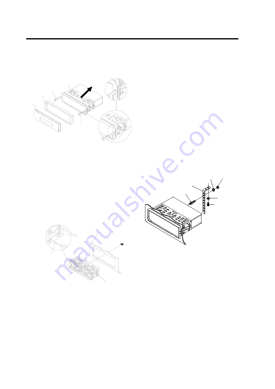
6.  Mount the sleeve by inserting the sleeve 

into the opening of the dashboard and 

bend open the tabs located around the 
sleeve with a screwdriver. Not all tabs 

will be able to make contact, so 

examine which ones will be most 
effective. Bending open the appropriate 

tabs behind the dashboard to secure 

the sleeve in place. 

Tabs

Screwdriver

Sleeve

Dashboard


7.  Reconnect the wire harness and the 

antenna and be careful not to pinch any 

wires or cables. 

8.  Slide the unit into the sleeve until it 

locks into place. 

9.  To further secure the unit, use the 

supplied metal strap to secure the   


back of the unit in place. Use the 

supplied hardware (Hex Nut (M5mm) 
and Spring Washer) to attach one end of 

the strap to the mounting bolt on the back 

of the unit. If necessary, bend the metal 
strap to fit your vehicle’s mounting area. 

Then use the supplied hardware 

(Tapping Screw (5x25mm) and Plain 
Washer) to attach the other end of metal 

strap to a solid metal part of the vehicle 

under the dashboard. This strap also 
helps ensure proper electrical grounding 

of the unit. 
Note to install the short threading 
terminal of the mounting bolt to the back 
of the unit and the other long threading 
terminal to the dashboard.   

Mounting Bolt

Spring Washer

Plain Washer

Tapping Screw

Hex Nut

Metal Strap


10.   Reconnect the cable to the vehicle 

battery’s negative (-) terminal. Then 
replace the outer trim ring and install the 

unit’s front panel (see the steps of 

“installing the front panel”). 


Removing the unit


1. Make sure the ignition is turned off, then 

disconnect the cable from the vehicle 
battery’s negative (-) terminal. 

2. Remove the metal strap attached the 

back of the unit (if attached). 

3. Press the release button to remove the   

Outer Trim Ring

Front Panel

L Key

Sleeve

R Key

Summary of Contents for AQMP70BTS

Page 1: ...reo Radio Automatic Memory Storing USB SD MMC Card Interface Fold Down Detachable Panel Auxiliary Input Function Bluetooth Hands free function A2DP Advanced Audio Distribution Profile Stereo Audio Tra...

Page 2: ...he frequency band 10 Selecting a station 10 Automatic memory storing program scanning 10 Scan 10 Station storing 10 USB play operation 10 Switching to USB mode 10 Selecting files 10 Pausing playing 10...

Page 3: ...or from hot air from the heater or where it would be subject to dust dirt or excessive vibration DIN FRONT REAR MOUNT This unit can be properly installed either from Front conventional DIN Front mount...

Page 4: ...end of the strap to the mounting bolt on the back of the unit If necessary bend the metal strap to fit your vehicle s mounting area Then use the supplied hardware Tapping Screw 5x25mm and Plain Washe...

Page 5: ...the screw holes marked T Toyota N Nissan located on both sides of the unit to fasten the unit to the factory radio mounting brackets supplied with your vehicle Dashboard or Console Screw Factory Radio...

Page 6: ...panel 2 Do not put pressure on the display or control buttons when removing or installing the front panel 3 Do not touch the contacts on the front panel or on the main unit body It may result in poor...

Page 7: ...7 WIRING CONNECTION ISO CONNECTION...

Page 8: ...DIR 6 4 RDM 7 1 8 MUTE 9 MODE 10 T MENU TRANS 11 2 INT 12 AUX IN 13 3 RPT 14 6 DIR 15 USB interface 16 9 LOC 17 8 EQ 18 SCAN 19 0 DSP 20 AS PS 21 7 MON 22 VOL SEL MENU Audio knob 23 hang up LOU BND 2...

Page 9: ...TION Shortly press MODE button 9 to change the unit working mode Radio USB CARD IPOD optional AUX and BT Audio SYSTEM SETTING Long press the SEL button 22 on the front panel to enter SYSTEM SETTING mo...

Page 10: ...20 shortly to scan preset station And the corresponding station number P1 P6 will flash on LCD SCAN Press SCAN button 18 to enter scan mode the unit will scan all the frequency rang and keep on each...

Page 11: ...el of the unit there is an USB interface 15 You can connect an USB driver through this interface 15 When you connect an USB driver through the interface the unit will search the MP3 files or WMA files...

Page 12: ...nnection 3 When you press button 1 to release the front panel the connection will be break off When you install the front panel you need to reconnection 4 If you turn off the mobile phone that has pai...

Page 13: ...MENU button 10 to transfer the phone call between the mobile phone and the unit Note 1 If you transfer the call to mobile phone the mute of the present mode will be released at the same time 2 When m...

Page 14: ...ting is established you are ready to using the Apps and the unit LCD will displaying controlled by smartphone all the times until you shut down the radio view Apps Click enter into the radio interface...

Page 15: ...e tunner settings Click enter into the USB mode If no USB all the icons will be in grey and can t be touch music file name in the USB Previous or next song the current process status of the playing Ti...

Page 16: ...inferface Click enter into the Bluetooth A2DP interface as follow Song name the previous or next song the current process status of the playing Time have already played The total time of the song If n...

Page 17: ...OL Volume Up Button Character Select A B 8 9 0 For MP3 WMA Operation 20 SEL LOU ENT Sound Mode Select Button Character Shift Right For MP3 WMA Operation Loudness Button When pressed long Enter Button...

Page 18: ...7 D x 50 H Tone Controls Bass at 100 Hz 10 dB Treble at 10 kHz 10 dB Maximum Output Power 4x60watts Current Drain 15 Ampere max RADIO U S A FM Frequency Coverage 87 5 108 MHz IF 10 7MHz Sensitivity S...

Page 19: ...ure return to normal Condensation Leave the player off for an hour or so then try again No sound Volume is in minimum Adjust volume to a desired level Wiring is not properly connected Check wiring con...

Reviews: