


3: Installation of xSenso
xSenso User Guide
23
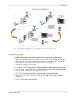
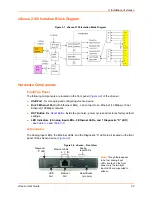
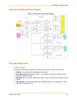
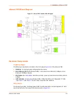
xSenso 2100 Isolation Block Diagram
Figure 3-1 xSenso 2100 Isolation Block Diagram
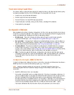
Hardware Components
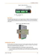
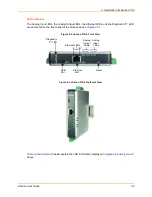
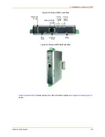
Front/Top Panel
The following components are located on the front panel (
Figure 3-2
) of the xSenso :
USB Port
- for managing and configuring xSenso device.
RJ-45 Ethernet Port
(with Ethernet LEDs) - can connect to an Ethernet (10 Mbps) or Fast
Ethernet (100 Mbps) network.
RST Button
(the
Reset Button
inside the pin hole) - power cycles and restores factory default
settings.
LED Indicators (2 Analog Input LEDs, 2 Ethernet LEDs, and 1 Diagnostic “X” LED
)
- see
Table 3-4
and
Table 3-5
.
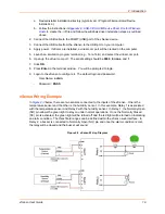
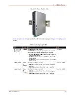
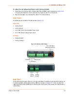
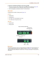
LED Indicators
The Analog Input LEDs, the Ethernet LEDs, and the Diagnostic “X” LED are all located on the front
panel of the xSenso device (
Figure 3-2
).
Figure 3-2 xSenso , Front View
Analog
Input LEDs
USB Ethernet Reset Button
Port Port (pin hole)
Ethernet LEDs
L R
Note:
Though there appear
to be four analog input
LEDs located on the front
panel, only the two right
Input LEDs are supported in
xSenso .
Diagnostic
“X” LED