background image

www.lanpro.com

Cabling Management - Gabinets & Racks -  Rack Accessories -  KVM - LP-RU07KVXX Series  KVM with 4, 8 and 16 Port 

PS2/USB Capable Switch with 15, 17 or 19 inch LCD Monitor. User Manual. 

12

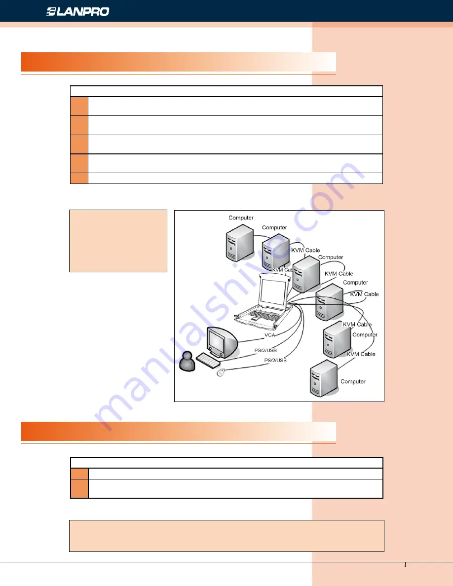
Figure 20

Single Stage Installation

Cascade Installation

To set up your installation, do the following:

1

Plug your USB / PS/2 keyboard, USB / PS/2 mouse and monitor into the console port 

section located on the unit’s rear panel.

2

Using a KVM cable set, plug the DB 15 connector into any available CPU port on the 

switch.

3

At  the  other  end  of  the  cable,  plug  the  keyboard,  mouse,  video  cables  into  their 

respective ports on the computer.

4

Plug the power adapter cable into the switch’s power jack, then plug the power 

adapter into an AC power source.

5

Repeat step 2-4 for any other computers you are connecting up.

To set up cascade installation, do the following:

1

Set up single installation as mentioned in SINGLE STAGE INSTALLATION.

2

Connect one end of HDB15 cable to IN port of upper KVM, and the other end to OUT 

port of lower KVM.

This completes the single stage installation, and you can turn on the power to the computers.

This completes the cascade installation, and you can turn on the power to the computers.

NOTE:

The  LCD  KVM  switch 

initially links to computer 

connected  to  the  first 

CPU port.

NOTE:

The LCD KVM switch initially links to computer connected to the first CPU port.

Summary of Contents for LP-RU07KVXX

Page 1: ...LPRU07KVXX_UM_ENB01W LP RU07KVXX Series KVM with 4 8 and 16 Port PS2 USB Capable Switch with 15 17 or 19 inch LCD Monitor User Manual LP RU07KVXX KVM Series with 4 8 and 16 Port PS2 USB Capable Switc...

Page 2: ...Port to connect computer 5 Note For operation of IP Module please refer to the related user manuals 6 DIMENSIONS 6 KVM SWITCHES PACKING LIST 7 KVM CONTROL PLATFORM CONNECTING CABLE 7 KVM CONTROL PLAT...

Page 3: ...connection It is easy and quick to install Just connect the cable to the correct port without software configuration So there is no difficulty and incompatibility in the installation The KVM switch pr...

Page 4: ...tems WIN95 98 98SE ME 200 XP WIN 7 WIN NT UNIX LINUX Type OSD Function Description LP RU07KV150 No 15 inches LCD screen keyboard and mouse for KVM Width 19 inches Depth 503 6 mm Height 1 U with 15 LCD...

Page 5: ...RU07KV150 LP RU07KV170 LP RU07KV190 with IP module LP RU07KV152 LP RU07KV172 LP RU07KV192 with IP module LP RU07KV15 LP RU07KV17 LP RU07KV19 with IP module View of product Rear View Figure 1 Front Vi...

Page 6: ...n be plugged into it to be connected to the LAN including the controlling computer 3 IP Module Reset If the IP module has no responding plug needle or ballpoint pen into the hole to reset it 4 Power J...

Page 7: ...grated KVM switch with multiple ports 4 8 16ports LP RU07KV19X Series Products KVM Control Platform 1 19 inches LCD screen keyboard and mouse control platform integrated KVM switch with multiple ports...

Page 8: ...tor User Manual 8 KVM Control Platform Power Cable Figure 8 AC Power Cable Figure 9 Figure 10 Before Use During Use Make sure all the devices are safely grounded Make sure the KVM wire and power cable...

Page 9: ...onnecting port Power on Close LCD panel and lock the front panel Release guide lock Push the control panel into the cabinet totally and then it is power off Reboot If the KVM switch does not respond j...

Page 10: ...User Manual 10 Figure 12 Figure 14 Figure 13 Figure 15 Figure 16 Assembling Disassembling The device can be assembled and disassembled as following 1 Screw the front flange to the rack first Slide th...

Page 11: ...Figure 17 Figure 18 Figure 19 2 Slide the switch onto the support flanges Use the screws supplied with this package to loosely attach the front of the switch to the front of the rack 3 Slide the rear...

Page 12: ...r respective ports on the computer 4 Plug the power adapter cable into the switch s power jack then plug the power adapter into an AC power source 5 Repeat step 2 4 for any other computers you are con...

Page 13: ...s start from the OSD main menu To pop up the main menu tap the Scroll Lock twice If OSD menu is set as console locked you must input password each time the main menu appears If no password has been se...

Page 14: ...er selecting a port the OSD menu automatically disappear and a blue tip window appears to indicate the port currently selected OSD functions are used to configure and control the OSD For example you c...

Page 15: ...ting on the main screen with this function The choices and their meanings are given in the table below Choice Meaning ALL Lists all of the ports on the installation QVIEW Lists only the ports that hav...

Page 16: ...screen will remind users CLEAR THE NAME LIST Clear the names of port list You need to enter password to clear the names of port list RESTORE DEFAULT VALUE Restore settings to default value You need t...

Reviews: