R6S User Manual
84
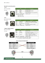
DC to DC Converter Description
Front
M12 K-Code Male
DC Input
PIN
Description
PIN 1
GND
Primary Ground
PIN 2
DC_IN
DC Power Input (Isolated)
PIN 3
GND
Primary Ground
PIN 4
IGN_IN
Power ON Trigger form car ignition ON
PIN 5 (PE)
CHASSIS GND
Chassis Ground
Note: SKU A: DC 32~96V
SKU B: DC 24~36V
SKU C: DC 72~110V
Rear
M12 K-Code Female
DC Output
PIN
Description
PIN 1
IGN_OUT
Adapter Ignition on Trigger Signal
PIN 2
MCU_PG
MCU Power_good detect pin (Isolated)
PIN 3
DC 54V Output
54V Output
PIN 4
GND
Secondary Ground (S_G for NVR)
PIN 5 (PE)
CHASSIS GND
Chassis Ground
System / NVR Description
M12 K-Code Male
DC Input
PIN
Description
PIN 1
GND
Signal Ground
PIN 2
DC_IN
DC Power Input (from DC converter, 52V)
PIN 3
MCU_PG
System Power Good Status
(without isolated because EMI solution)
PIN 4
IGN_IN
Ignition on Trigger Form Adapter
(Ignition voltage support: 12V or 24V)
PIN 5 (PE)
CHASSIS GND
Chassis Ground
Note: DC_in, below 44V without PoE power support
DC_in, above 45V enable PoE power support
Summary of Contents for R6S
Page 1: ...1 R6S User Manual Version 1 6 Date of Release 2022 05 04 ...
Page 8: ...R6S User Manual 8 ...
Page 17: ...R6S User Manual 17 ...
Page 18: ...R6S User Manual 18 Front View ...
Page 19: ...R6S User Manual 19 Rear View ...
Page 20: ...R6S User Manual 20 Front View ...
Page 21: ...R6S User Manual 21 Rear View ...
Page 22: ...R6S User Manual 22 Front View ...
Page 23: ...R6S User Manual 23 Rear View ...
Page 24: ...R6S User Manual 24 ...
Page 25: ...R6S User Manual 25 B SKU C SKU ...
Page 26: ...R6S User Manual 26 ...
Page 27: ...R6S User Manual 27 ...
Page 28: ...R6S User Manual 28 ...
Page 35: ...R6S User Manual 35 ...
Page 38: ...R6S User Manual 38 ...
Page 42: ...R6S User Manual 42 ...
Page 49: ...R6S User Manual 49 ...
Page 56: ...R6S User Manual 56 ...
Page 60: ...R6S User Manual 60 ...
Page 66: ...R6S User Manual 66 ...
Page 73: ...R6S User Manual 73 ...
Page 86: ...R6S User Manual 86 Example ...
Page 87: ...R6S User Manual 87 ...

