


Page: 10
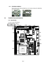
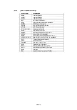
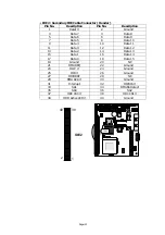
2.2.3 I/O Connectors Summary
LOCATION
FUNCTION
LAN1
LAN Connector
LAN2
LAN Connector
LAN3
LAN Connector
PS1
AT Power Connector
KM1
PS/2 Keyboard & Mouse Connector
PWR1
HDD Power Connector
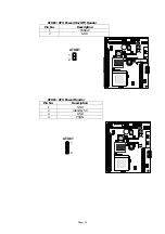
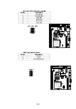
ATXB1
ATX Power(On/Off) Header
ATXC1
ATX Power Header
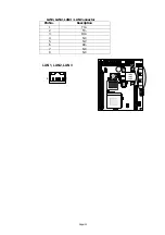
JP1
、
JP2
、
JP3
Extension LAN LED
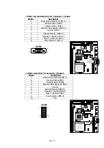
FAN1
CPU FAN Connector
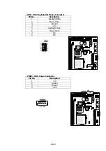
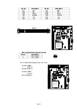
COM1
RS-232 Serial Port #1 Connector
COM2
Serial Port #2 Connector
CON1
Power LED, Reset, Speaker Connector
USB1
、
2
、
3
、
4
USB Port#1 & #2 & #3 & #4 Connector
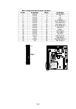
FDC1
Floppy Interface Connector
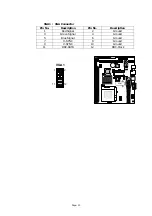
VGA1
VGA Connector
ATXPS1
ATX Power Connector
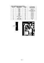
LPT1
Parallel Port Connector
IDE1
Primary IDE Cable Connector
IDE2
Secondary IDE Cable Connector
PCI1
PCI Slot
SR1
System Status Signal (port 440)
Summary of Contents for EM-561 Series
Page 4: ......
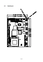
Page 7: ...Page 3 1 5 Board Layout...
Page 52: ...Page 48 Setp 4 Setp 5 Setp6 Click Yes Click Next Click Finish...
Page 54: ...Page 50 Setp 4 Setp 5 Setp 6 Click Next Click Next Click Finish...
Page 60: ...Page 56 Setp 8 Setp 9 Setp 10 Click Next 2 Click OK Click OK 1 Put win98 CD ROM...
Page 61: ...Page 57 Setp 11 Click Finish...


