Lanier lp145n Hardware Manual Download Page 144

Consumables

133

10

Consumables

Important

Our products are engineered to meet the highest standards of quality and
functionality. When purchasing expendable supplies, we recommend using
only those specified by an authorized dealer.
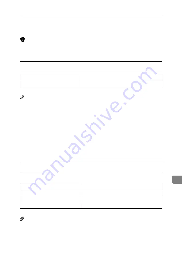
Toner Cartridge

*1

A4/letter 5% test chart, 2 pages/job

Note

If toner cartridges are not changed when necessary, printing will become im-
possible. We recommend keeping a stock of bottles or purchasing them soon.

The actual number of printable pages varies depending on the image volume
and density, number of pages to be printed at a time, paper type and paper
size used, and environmental conditions such as temperature and humidity.

Toner cartridges may need to be changed sooner than indicated above due to
deterioration over the period of use.

Toner cartridges (consumables) are not covered by warranty. However, if
there is problem, contact the store where they were purchased.

When you first use this printer, use the toner cartridge packaged with the
printer.

Maintenance Kit

Maintenance Kit SP 8100A

*1

A4/letter 5% test chart, 2 pages/job

Note

The actual number of printable pages varies depending on the image volume
and density, number of pages to be printed at a time, paper type and paper
size used, and environmental conditions such as temperature and humidity.

The maintenance kit (consumables) are not covered by warranty. However, if
there is problem, contact the store where they were purchased.

Toner cartridge

Average printable number of pages per bottle 

*1 

Black

30,000 pages 

Name

Average printable number of pages 

*1 

Development Unit

150,000 pages

Fusing Unit

150,000 pages

Transfer Unit

150,000 pages

Summary of Contents for lp145n

Page 1: ...ence For safe and correct use be sure to read the Safety Information before using the machine Guide to the Printer Installing Options Connecting the Printer Configuration Paper and Other Media Replaci...

Page 2: ...t be trademarks of their respective companies We disclaim any and all rights to those marks The proper names of the Windows operating systems are as follows Microsoft Windows 95 operating system Micro...

Page 3: ...y please follow the instructions and handle the machine as indicated High temperature parts Turn off the main power and be careful when replacing fusing unit removing misfed paper The surface of the f...

Page 4: ...Quick Installation Guide Contains procedures for removing the printer from its box connecting it to a computer and installing its driver Hardware Guide Contains information about paper and procedures...

Page 5: ...ead these notes They can be found in the Safety Information Indicates points to pay attention to when using the machine and explanations of likely causes of paper misfeeds damage to originals or loss...

Page 6: ...the printer for the specified models This explains about the 220 240 V model printer Read if you purchase this model This explains about the 120 V model printer Read if you purchase this model Note Yo...

Page 7: ...rectory C Select an interface language and then click OK D Click Install manuals E Follow the instructions on the screen to complete the installation F Click Finish when the installation is completed...

Page 8: ...Paper Feed Unit PB 3020 10 Attaching User Account Enhance Unit Type E 16 Attaching Printer Hard Disk Drive Type 8100 20 Attaching Memory Unit Type D 128MB Memory Unit Type E 256MB SDRAM Module 27 Atta...

Page 9: ...s Tray 79 Switching between Paper Trays 85 6 Replacing Consumables Replacing the Toner Cartridge 87 Adding Staples 92 7 Adjusting the Printer Adjusting the Image Density 95 Adjusting Tray Registration...

Page 10: ...ix 10 Appendix Moving and Transporting the Printer 131 Moving the Printer 132 Consumables 133 Toner Cartridge 133 Maintenance Kit 133 Specifications 134 Mainframe 134 Options 137 INDEX 143...

Page 11: ...x...

Page 12: ...nsion card slot Insert an optional unit into a slot 6 Power Switch Use this switch to turn the printer power on and off 7 Output Tray Printed output is stacked here with the print side face down 8 Con...

Page 13: ...sheets of plain paper 80 g m2 20 lb 4 Upper Vertical Paper Feed Cover Open this cover when accessing the in side of the printer If you install the optional Large Capacity Tray RT45 remove this cover 5...

Page 14: ...n up the lever when replacing the toner 4 Toner Holder Slide this out when replacing the toner 5 Development Unit When Replace Maintenance Kit ap pears on the panel display replace this unit 6 Right C...

Page 15: ...if the printer is online 6 Power Indicator Is on when the printer power is on Is off when the power is off or when the printer is in Energy Saver mode 7 Alert Indicator Blinks or lights up whenever a...

Page 16: ...Unit Type E 256MB User Account Enhance Unit Type E IEEE 802 11b Interface Unit IEEE 1284 Interface Board Type A Gigabit Ethernet Board Type A Printer Hard Disk Drive Type 8100 VM Card Type D Data Sto...

Page 17: ...isk drive to the controller board F Install the SDRAM module Memory Unit Type D 128MB Memory Unit Type E 256MB Install the module to the SDRAM module slot on the controller board There are two types o...

Page 18: ...your sales or service representative 3 Bridge Unit Type 2045 This unit is necessary when using the Finisher If you want to install the Bridge Unit Type 2045 contact your sales or serv ice representati...

Page 19: ...d Type A See p 38 Attaching Gigabit Ethernet Board 3 Optional units See p 41 Attaching VM Card Type D See p 43 Attaching Data Storage Card Type A 4 Printer Hard Disk Drive Type 8100 See p 20 Attaching...

Page 20: ...alling options If you slide out the controller board to install units carefully read the instruction to re install the controller board Important The following may occur if the controller board is not...

Page 21: ...ng Paper Feed Unit PB 3020 1 Screw 2 Knob Screw Finger type 3 Lock Plate Before moving the machine unplug the power cord from the outlet If the cord is unplugged abruptly it could become damaged Damag...

Page 22: ...s unplugged from the wall outlet C Remove the tape that holds the paper feed unit and then remove the pack ing material Do not remove the tape that holds the connector cable inside the connector cover...

Page 23: ...e held by least two people When lifting the printer pull out the grips from the front of the printer One person should hold the grips on the front and another person should hold the grips on the rear...

Page 24: ...it stops After that lift it slightly and then pull it out G Pull out the first paper tray Tray 1 and take the screwdriver 1 from the tray H Lock the Paper Bank and the printer with the screw Be sure t...

Page 25: ...inside 2 and then fasten the plate with the knob screw using your fingers J Close the lower vertical paper feed cover K Open the connector cover 2 remove the tape that holds the connector ca ble and...

Page 26: ...rly reinstall it following this procedure If you cannot install it properly even after attempting reinstal lation contact your sales or service representative Reference For printing the configuration...

Page 27: ...mage User Account Enhance Unit Do not subject User Account Enhance Unit to physical shocks A Check the package contains the following User Account Enhance Unit Type E B Turn off the printer C Pull out...

Page 28: ...17 2 D Remove the screws as shown by turning them counterclockwise using the provided screwdriver E Hold the part 1 of the controller board and then slide it out completely F Place the controller boar...

Page 29: ...nce Unit as shown H Align the notch of User Account Enhance Unit and then insert it into the controller board pressing it down until it clicks into place I Make sure that User Account Enhance Unit is...

Page 30: ...tion you can check whether the User Account En hance Unit is properly installed Print the configuration page from the List Test Print menu If it is installed properly Accounting Module will appear for...

Page 31: ...something metal to discharge any static electricity Static electricity can damage the hard disk drive Do not subject the hard disk drive to physical shocks Before using the new hard disk drive be sure...

Page 32: ...100 21 2 Power Cable Supplied Screws Protective Sheet B Turn off the printer C Pull out the first paper tray Tray 1 and take the screwdriver 1 from the tray Each screw to be removed requires this scre...

Page 33: ...e the screws as shown by turning them counterclockwise using the provided screwdriver E Hold the part 1 of the controller board and then slide it out completely F Place the controller board on a flat...

Page 34: ...on both sides 1 to remove the SDRAM module 2 Be sure not to leave any SDRAM module in the slots Doing so may damage SDRAM modules when installing the hard disk drive H Place the protective sheet on th...

Page 35: ...ive s casing Hook this part over the flange curled part in the slot 1 on the controller board and then align 2 and 3 with the screw holes in the rear edge of the controller board K Fasten the screws c...

Page 36: ...the printer and attach an SDRAM module N Remove the protective sheet when installing the hard disk drive is com pleted Be sure to check whether the hard disk drive is completely secured before re movi...

Page 37: ...fter using it After finishing installation you can check whether the hard disk drive is properly installed Print the configuration page from the List Test Print menu If it is installed properly Printe...

Page 38: ...scharge any static electricity Static electricity can damage the memory unit Do not subject the memory unit to physical shocks Available memory varies depending on a model type Before using the new me...

Page 39: ...e the screws as shown by turning them counterclockwise using the provided screwdriver D Hold the part 1 of the controller board and then slide it out completely E Place the controller board on a flat...

Page 40: ...fault SDRAM module is installed in the inner slot To install an additional memory attach an additional SDRAM module to the outer slot or replace the default SDRAM module G When installing an SDRAM mod...

Page 41: ...512 MB remove the default SDRAM module and then install two 256 MB SDRAM modules J Store the controller board 1 into the printer while gently pressing the cover 2 Push in the controller board firmly...

Page 42: ...capacity will appear under Total Memo ry on the configuration page The table below shows the total SDRAM module capacities If the memory unit is not properly installed repeat this procedure If you can...

Page 43: ...tion because of memory shortage Before touching the 802 11b interface unit touch something metal to dis charge any static electricity Static electricity can damage the 802 11b interface unit Do not su...

Page 44: ...er cable C Remove the screw by turning it counterclockwise using the provided screwdriver and then remove the cover of the 802 11b interface board slot The removed cover is not used when installing th...

Page 45: ...cure the interface board F Attach the antenna to the card with the label facing down and the uneven side of the antenna facing up G With the antenna and the indented end toward you slowly insert the i...

Page 46: ...ge from the List Test Print menu If it is installed properly IEEE 802 11b will appear for Device Connection on the configuration page If the 802 11b interface unit is not installed properly reinstall...

Page 47: ...physical shocks A Check the package contains the following IEEE 1284 Interface Board Type A B Turn off the power and then unplug the power cable C Remove the screw by turning it counterclockwise using...

Page 48: ...can check the 1284 interface board is prop erly installed Print the configuration page from the List Test Print menu If it is installed properly Parallel Interface will appear for Device Con nection o...

Page 49: ...he board Before handling the gigabit ethernet board ground yourself by touching something metal to discharge any static electricity Static electricity can dam age the gigabit ethernet board Do not sub...

Page 50: ...ver each port with its protective cap D Remove the screw by turning it counterclockwise using the provided screwdriver and then remove the cover of the Gigabit ethernet board slot The removed cover is...

Page 51: ...will see Gigabit Ethernet Board for Device Connection on the configuration page If the Gigabit ethernet board is not installed properly reinstall it following this procedure If you cannot install it p...

Page 52: ...and also it does not function because of memory shortage Protect VM Card Type D from physical shocks Using the upper slot is recommended for inserting the unit A Check the package contains the followi...

Page 53: ...Installing Options 42 2 Note Do not touch the VM card while the printer is in use It may come loose even if pushed only slightly...

Page 54: ...A Check the package contains the following Data Storage Card Type A B Turn off the power and then unplug the power cable C Remove the cover of the expansion card slot D Carefully insert the data stor...

Page 55: ...Installing Options 44 2...

Page 56: ...et board which supports 1000BASE T is available Important Use shielded Ethernet cable Unshielded cables create electromagnetic inter ference that could cause malfunctions The Ethernet cable is not sup...

Page 57: ...s shown B Connect the ethernet cable to the gigabit ethernet board C Connect the other end of the cable to the printer s network such as a hub Note The printer s ethernet and USB ports are not availab...

Page 58: ...perly connected to the net work 2 Yellow comes on when 100BASE TX is being used It comes off when 10BASE T is being used For gigabit ethernet board 1 Yellow comes on 100BASE TX is being used Green and...

Page 59: ...tor of the USB2 0 cable to the USB port B If the gigabit ethernet board is attached connect the square shaped connec tor of the USB2 0 cable to the USB port of the board The printer s ethernet and USB...

Page 60: ...e shielded interface cable Unshielded cables create electromagnetic inter ference that could cause malfunctions Voltage rating of the computer s parallel port DC 5 V max A Turn off the printer and com...

Page 61: ...Connecting the Printer 50 3...

Page 62: ...following table shows the control panel settings and their default values These items appear in the Host Interface menu Note If DHCP is in use the IP address subnet mask and gateway address are all se...

Page 63: ...Active Protocol using T or U and then press the q Enter key E Select the network protocol using T or U and then press the q Enter key F Select Active or Not Active using T or U and then press the q E...

Page 64: ...nd Gateway Address J Enter the address using T or U and then press the q Enter key Press the T or U key to enter the left most entry field of the address After entering the left field press the V key...

Page 65: ...annot make settings for the following items IP Address Subnet Mask Gateway Address Consult your network administrator for information about making network settings A Press the Menu key B Select Host I...

Page 66: ...configuration page see Printing the Test Page Quick Installation Guide Making Network Settings for Using Netware If you use NetWare select the frame type for NetWare Select one of the items below if n...

Page 67: ...key D Select Frame Type NW using T or U and then press the q Enter key E Select the frame type using T or U and then press the q Enter key F Press the Menu key to return to the initial screen G Print...

Page 68: ...ction because of memory shortage To use IEEE 802 11b Wireless LAN set as the followings using the control panel press the Menu key and then select Host Interface Network Setup LAN Type and then IEEE 8...

Page 69: ...802 11 Ad hoc To use an IEEE 802 11b card for which the SSID Network Name setting is not necessary select Ad hoc The transmission mode of IEEE 802 11b can also be set using a Web brows er For details...

Page 70: ...inting the Test Page Quick Installation Guide Setting SSID If Infrastructure or 802 11 Ad hoc is selected for Comm Mode set SSID to use for transmission Confirm the network administrator for SSID to u...

Page 71: ...Printing the Test Page Quick Installation Guide Setting a WEP key In the case of using a WEP key on a network activate the WEP setting to be used for communication along with WEP Confirm the network a...

Page 72: ...used for hexadecimal and up to 13 characters for ASCII The number of characters that can be entered is limited to 10 or 26 for hexa decimal and 5 or 13 for ASCII For ASCII character strings each capit...

Page 73: ...Configuration 62 4...

Page 74: ...ful of the paper feed direction The direction is determined for each pa per size Input Paper Sizes In this manual On the display Paper feed direction L Feed direction A4 8 1 2 11 Short edge feed direc...

Page 75: ...size setting using the control panel Tray 1 2 or the Paper Feed Unit Tray 3 4 do not support custom size The following sizes are supported Bypass Tray approximately 100 297 mm in width and 148 600 mm...

Page 76: ...e paper size using the control panel Feed Direction Size inch Bypass Tray Tray 1 2 Paper Feed Unit Tray 3 4 Large Capacity Tray Duplex Printing A3 L 11 7 16 6 B4 L 10 2 14 4 A4 L 8 3 11 7 A4 K 11 69 8...

Page 77: ...custom size The following sizes are supported Bypass Tray approximately 3 94 11 70 in width and 5 83 23 62 in length The size is not supported Paper weight and number of sheets to be set Check that th...

Page 78: ...ass Tray Print side facing down Paper Feed Unit Print side facing up Print quality cannot be guaranteed if paper other than the ones recommended is used For more information about recommended paper co...

Page 79: ...s not stacked higher than the paper guides in side the bypass tray Duplex printing Possible Printer setup Press the Menu key select Paper Input and then select Letterhead for the selected tray s paper...

Page 80: ...in side the bypass tray Duplex printing Not possible Additional cautions Print speed is slightly slower compared to plain paper Printer setup Make the following settings using the control panel Press...

Page 81: ...r Paper whose weight is heavier or lighter than the limitation Paper with windows holes perforations cutouts or embossing Adhesive label paper on which glue or base paper is exposed Paper with clips o...

Page 82: ...tray Tray 1 The same procedure can be used for the optional paper feed unit Important Make sure paper is not stacked above the limit mark inside the tray Misfeeds might occur Do not put different type...

Page 83: ...to the new paper size E Align all four sides of the paper stack and load it into the tray with the print side up Confirm that the top of the stack is not higher than the limit mark inside the tray If...

Page 84: ...he holder in the tray G Lock the side lever H Adjust the paper size dial to match the size and feed direction of the paper in the paper tray Be sure to set the dial to the correct direction to avoid p...

Page 85: ...see p 67 Paper Recommendations Loading Paper in the Optional Large Capacity Tray This section describes instructions to load paper in the optional Large Capacity Tray RT45 A Check if the tray release...

Page 86: ...the stack to the wall Confirm the top of the stack is not higher than the limit mark inside the tray D Close the top cover Note If the printer is in the Energy Saver mode when changing the paper size...

Page 87: ...ze for Tray 1 2 or Tray 3 4 optional paper feed unit Use the bypass tray if you load paper in custom size and set by pass tray s paper size using the control panel A Press the Menu key B Select Paper...

Page 88: ...ting the Paper Size Automatically Important If you specify the paper size using the control panel and want to return the settings to load paper size automatically load paper into the paper tray and fo...

Page 89: ...ce by selecting the optimum paper type for the tray You can select from the following paper types Plain Paper Recycled Paper Special Paper Color Paper Letterhead Pre printed Prepunched Bond Paper Card...

Page 90: ...er in the Bypass Tray Important Shuffle the paper before loading the stack onto the tray so multiple sheets are not fed in together Set the size and direction of the loaded paper on the control panel...

Page 91: ...des outwards and then load paper until it stops with the print side down Confirm that the top of the stack is not higher than the limit mark inside the tray Shuffle the paper before loading the stack...

Page 92: ...U and then press the q Enter key D Select the paper size you want to set using T or U and then press the q Enter key E Press the Menu key to return to the initial screen Note To load thick paper OHP t...

Page 93: ...varies depending on a type of printer drivers For details see the print er driver Help Be sure to set a same size using the control panel and the printer driver If you set different size printer erro...

Page 94: ...alue using T or U and then press the q Enter key Metric version You can set the vertical value in the following range 148 mm 432 mm 5 83 17 01 in By pressing the key the value increases or decreases b...

Page 95: ...labels thick paper envelopes or OHP transparencies in the bypass tray The paper type selected using the printer driver overrides that selected using the control panel Be sure to set a paper type usin...

Page 96: ...hen paper of the same size is loaded in both the standard tray and the paper feed unit option and when Aut Tray Select is set with the printer driver paper will be fed from the standard tray when you...

Page 97: ...Paper and Other Media 86 5 D Select the tray type you want to use using T or U and then press the q Enter key E Press the Menu key to return to the initial screen...

Page 98: ...sed and the toner cartridge out of reach of chil dren If toner or used toner is inhaled gargle with plenty of water and move into a fresh air environment Consult a doctor if necessary If your skin com...

Page 99: ...ents of your print images and printing environment conditions When to replace the toner cartridge If any of the toner cartridge indicators on the initial screen appear to show it is empty replace the...

Page 100: ...e lever to the right 1 hold the handle and gently slide the toner holder out 2 D Press the toner cartridge back to raise its top and then gently pull it out E Shake the new toner cartridge back and fo...

Page 101: ...he black cap from the bottle toner can scatter easily Do not shake or jar the bottle G Place the toner cartridge on the toner holder 1 and then pull its head to ward you 2 to lock it in place H Slide...

Page 102: ...d malfunction do not turn off the power until Ready appears on the display Note Cooperate with the Toner cartridge Recycling Program whereby are col lected used toner cartridges For details consult wi...

Page 103: ...to replace the staple refill with a new one Important After adding the staple refill staples might not be ejected for the first few times A Open the front cover of the Finisher SR 3040 The cartridge c...

Page 104: ...ides of the cartridge and then pull up the upper unit of it D Take out the empty refill in the arrow direction E Align the arrows on the new refill and the cartridge and then push in the refill until...

Page 105: ...les 94 6 F Gently push down the upper unit into the cartridge G Pull out the ribbon H Hold the green lever while pushing in the cartridge until it clicks I Close the front cover of the finisher AQV705...

Page 106: ...age density is not appropriate A Press the Menu key B Select Maintenance using T or U and then press the q Enter key C Select Image Density using T or U and then press the q Enter key D Specify the im...

Page 107: ...unit or the duplex unit is installed updating is useful in some cases A Press the Menu key B Select Maintenance using T or U and then press the q Enter key C Select Registration using T or U and then...

Page 108: ...his setting adjust the margins of the test sheet so that they are equal in size G In the Registration menu Select Adjustment using T or U and then press the q Enter key H Select the parameter you want...

Page 109: ...e negative direction A Print Area B Feed Direction Pressing the U or T key makes the value increase or decrease by 1 0 mm steps J Press the q Enter key The display returns to the print area Adjustment...

Page 110: ...inter and turn it on again to recover Offline The printer is offline To start printing switch the printer online by pressing the Online key Please wait This message may appear for a few seconds It mea...

Page 111: ...witch off then on If the problem does not solve contact your sales service representa tives Hardware Problem Tray 1 or greater number There is a problem with the paper transfer mo tor of paper tray 1...

Page 112: ...cable con nected securely to the printer and the computer Connect the interface cable securely If it has a fastener fasten it securely as well Are you using the correct interface cable The type of int...

Page 113: ...Print to the following port box to confirm that the correct port is se lected Note Due to the termination of support for Windows 95 98 by Microsoft the supplier does not guarantee any problem change o...

Page 114: ...ext on the File menu click Properties E Click the Port tab F Check the Print to the following port s box to confirm that the correct port is selected Windows NT 4 0 A Click Start point to Settings and...

Page 115: ...e sure there are no gaps See p 71 Loading Paper Paper is either too thick or too thin See p 63 Paper and Other Media Paper is bent or wrinkled Use paper that have no bents or wrinkles See p 63 Paper a...

Page 116: ...o turn on the printer If the printer is turned off while it is still accessing the hard disk for example during file deletion the printer will re quire more time to power up the next time it is turned...

Page 117: ...the printer driver Help The print out image is missing or partially blurred Paper is damp Use paper that has been stored properly See p 63 Paper and Other Media Toner is almost depleted When the Add...

Page 118: ...on roller is dirty Clean the registration roller Contact your sales service representatives PDF Direct Print is not executed PDF file is not printed You must install an optional hard disk drive or set...

Page 119: ...dicating a paper size appears either place the indicated size in the paper tray or perform Form Feed Also if Sub Paper Size in the System Menu is set to Auto printing is performed assuming letter size...

Page 120: ...settings see Web Image Monitor Help Access the printer through the Web browser log on as an Administrator on the Web Image Monitor and then con firm the settings of the SMTP server in E mail For deta...

Page 121: ...er notification level arrives later e mail will not be sent even if the notifi cation level is changed after When no date information is in cluded in sent e mail the mail server has a malfunction Make...

Page 122: ...curled paper In this case try turning the paper over in the tray After removing the jammed staples staples might not be ejected for the first few times A Open the front cover of the Finisher SR 3040...

Page 123: ...Troubleshooting 112 8 C Pull up the cartridge s knob D Take out all staples slid from the cartridge E Pull down the cartridge s knob until it clicks AQV708S AQV709S AQV710S...

Page 124: ...Removing Jammed Staples 113 8 F Hold the green lever while pushing in the cartridge until it clicks G Close the front cover of the finisher AQV711S...

Page 125: ...e Punch function A Open the front cover of the finisher B Pull out the punch waste box and then remove punch waste C Reinstall the punch waste box If you do not Empty Punch Receptacle is still display...

Page 126: ...reinstall the punch waste box The message Empty Punch Receptacle may appear even when the punch waste box is not yet full If this happens the position of the punch waste box indicated by the arrow as...

Page 127: ...Troubleshooting 116 8...

Page 128: ...ea might be indicated In this case check every ap plicable area See the following charts shown in the illustration If paper continues to misfeed check the following points Confirm that the setting of...

Page 129: ...ge appears do the followings A Open the Bypass Tray 1 and then open the Duplex Unit by pushing the catch upwards 2 B Open the right cover by pushing the catch upwards If the optional Large Capacity Tr...

Page 130: ...cover D Remove misfed paper slowly E Close the lower vertical paper feed cover F Open the upper vertical paper feed cover If your printer is equipped with the optional Large Capacity Tray RT45 the up...

Page 131: ...e blue lever A2 in the right cover 1 remove the misfed pa per 2 I Open the Bypass Tray and then remove the misfed paper J Close the covers in the following order The upper vertical paper feed cover Th...

Page 132: ...D Inter Path message appears do the followings A Open the output feeder cover of the Bridge Unit 1 and then remove the misfed paper 2 B Open the Bypass Tray 1 and then open the Duplex Unit by pushing...

Page 133: ...per by turning the blue knob C as shown in the illustration If you turn the blue knob C clockwise 1 the misfed paper comes out to the output tray 2 If you turn the blue knob C counterclockwise 1 remov...

Page 134: ...and then remove the misfed pa per from inside the right cover 2 H Close the covers in the following order The right cover The Duplex Unit The Bypass Tray The front cover The output feeder cover I Ope...

Page 135: ...ppears When the Remove Misfeed R Finisher message appears do the followings A Open the upper cover and then remove misfed paper B If you cannot remove misfed paper open the slide cover and remove the...

Page 136: ...125 9 D Hold up the lever R1 and remove the misfed paper E Hold down the lever R2 and remove the misfed paper F If you cannot remove misfed paper hold down the lever R3 and remove the misfed paper AQ...

Page 137: ...ed Paper 126 9 G Hold down the lever R4 and remove the misfed paper H Pull the lever R5 and remove the misfed paper I When removing the misfed paper completed close the front cover of the finisher AQV...

Page 138: ...appears do the followings A Open the top cover of the Large Capacity Tray RT45 B Remove the misfed paper C If you cannot remove the misfed paper in the previous step close the top cover of the Large...

Page 139: ...Removing Misfed Paper 128 9 D Remove the misfed paper from the left side of the Large Capacity Tray RT45 E Slide the Large Capacity Tray RT45 forward to connect it to the printer AQV069S AQV052S...

Page 140: ...Bypass Tray and the Duplex Unit right cover and then remove the misfed paper B Close the Duplex Unit right cover C Open the Duplex Unit by pushing the catch upwards 1 D Open the cover Z to the left 1...

Page 141: ...Removing Misfed Paper 130 9...

Page 142: ...piece of machinery Take care to avoid damage dur ing shipment When moving the machine each person should hold the handles that are located on opposite sides and then lift it slowly Lifting it careles...

Page 143: ...horizontally to the place where you want to install it D If you removed options reinstall them Note Be sure to move the printer horizontally To prevent toner from scattering move the printer slowly If...

Page 144: ...cated above due to deterioration over the period of use Toner cartridges consumables are not covered by warranty However if there is problem contact the store where they were purchased When you first...

Page 145: ...4L 8 1 2 11L one sided duplex Printing speed may vary depending on the setting up environment Resolution 600 600 dpi RPCS PostScript 3 PCL 5e 6 300 300 dpi RPCS PostScript 3 PCL 5e Paper size See p 63...

Page 146: ...Paper Feed Unit PB 3020 Weight Approximately 64 kg 141 1 lb power cord included Printing 1 450 W or less No power is used during power off Energy Saver 6 W or less Printing 1 400 W or less No power is...

Page 147: ...Base TX USB2 0 It requires a USB computer port and cable that support USB 2 0 Optional IEEE 802 11b Wireless LAN Parallel Bidirectional IEEE1284 Gigabit Ethernet 1000Base T Printer Language RPCS PCL...

Page 148: ...x 25 kg 55 2 lb Note Specifications are subject to change without notice Large Capacity Tray RT45 Paper size See p 63 Paper and Other Media Supported by This Printer Paper weight See p 63 Paper and Ot...

Page 149: ...3 g m2 14 43 lb Stack capacity No Staple 2 000 sheets A4K 81 2 11 K 80 g m2 20 lb 750 sheets A3L B4 JISL A4L B5 JISKL 11 17 L 81 2 14 L 81 2 11 L 80 g m2 20 lb 500 sheets A5K 80 g m2 20 lb 100 sheets...

Page 150: ...2 holes A3L B4 JISL A4KL B5 JISKL A5KL 11 17 L letterKL 51 2 81 2 L legalL 71 4 101 2 KL 81 4 13 L 81 2 13 L 8 13 L Paper size 3 holes A3L B4 JISL A4K B5 JISK 11 17 L letterK Paper size 4 holes A3L B4...

Page 151: ...Script Type 1 and PostScript Type 2 To download them use Printer Utility for Mac User Account Enhance Unit Type E Capacity 128 KB Store User Code up to 500 users Memory Unit Type D 128MB Memory Unit T...

Page 152: ...eneral the transmittable dis tance indoors is 10 100 m depending on the environment Transmission Mode ad hoc mode and infrastructure mode IEEE 802 11b Interface Unit Type I This unit is for the follow...

Page 153: ...e IEEE 1284 Interface Board Type A Transmission Spec IEEE 1284 Required cable Standard IEEE 1284 compliant Micro Centronics 36 pin cable Gigabit Ethernet Board Type A Interface Connector Ethernet 10Ba...

Page 154: ...ess LAN Configuration 57 Connecting the Printer Network Connection 45 Parallel Connection 49 USB Connection 48 Consumables 133 D Data In Indicator 4 Development Unit 133 DHCP 54 Display panel messages...

Page 155: ...ve Misfed Paper Remove misfeed A Y paper tray 118 Remove misfeed B C D Inter Path 121 Remove misfeed R Finisher 124 Remove misfeed U LCT 127 Remove misfeed Z Duplex Unit 129 Removing Misfed Paper 117...

Page 156: ...Copyright 2006...

Page 157: ...Hardware Guide GB GB G147 8613...

Reviews: