background image

Concept


Concept Manual 

10

10

11

11

12

12

13

13

6

6

9

9

14

14

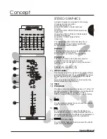
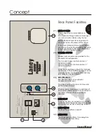
A Graphic Equaliser is provided for fine tuning 
of mixes and room acoustics 
Centre frequencies are 
80Hz,200Hz,600Hz,1.2KHz,3KHz and 
10.5KHz. 
Varying the 80Hz / 200Hz filters adjusts bass 
frequencies
Varying the 600Hz,1.2KHz and 3KHz adjusts 
midrange frequencies.
Varying the 10.5KHz adjusts treble 
frequencies.

The Graphic Equaliser is the last place the L + 
R Masters pass through before amplification 
by the internal power amplifiers.

STEREO GRAPHICS

This lamp illuminates when power is connected to 
your mixer and it is turned on.
A Power switch is located on the rear panel.

POWER

This lamp illuminates when phantom power is 
connected to all the microphone inputs.
Phantom power is switched on using a rear panel 
slide switch.

PHANTOM

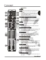
The `EFFECTS' fader controls the level of the effects 
signal sent to the Masters.

(Pre-fade listen)

FADER

FADER

The Mon control enables the user to send the effects 
signal to the monitor output 

PFL

PFL

MON

MON

In common with all other inputs PFL facilities are 
provided for the setting up of the effects.When PFL is 
enabled the signal from the effects unit is displayed on 
the right meter and is played in the headphones

TIME
PROGRAM

INPUT LEVEL

This controls level of the signal into the built in Effects 
processor.This provides the user the ability to achieve 
the best signal to noise performance of the effects 
unit.
There is peak led near this control to show that the 
Effects processor is near clipping.

The above controls allows the selection of 1 of the 127 
available programs.These programs are arranged into 
8 types selectable by the `Program' control.
Different  program times can then be selected using 

11)

12)

9)

14)

6)

13)

DIGITAL EFFECTS

DIGITAL FX

DIGITAL FX

PFL

PFL

PEAK

PEAK

INPUT 

INPUT 

PROGRAM

PROGRAM

TIME

TIME

MON

MON

Short

Short

Long

Long

Hall

Hall Dark Hall

Dark Hall

Room

Room

Dark Room

Dark Room

Plate

Plate

Dark Plate

Dark Plate

Delay Regen

Delay Regen

Reverse Reverb

Reverse Reverb

LEVEL

LEVEL

Gated Reverb

Gated Reverb

Delay

Delay

1

1

2

2

3

3

4

4

5

5

6

6

8

8

7

7

0

0

1

1

2

2

3

3

4

4

5

5

6

6

7

7

8

8

9

9

10

10

0

0

1

1

2

2

3

3

4

4

5

5

6

6

7

7

8

8

9

9

10

10

+10

+10

OdB

OdB

-6

-6

-10

-10

-20

-20

-30

-30

+6

+6

-

-

88

600Hz

600Hz

1K2Hz

1K2Hz

3KHz

3KHz

10KHz

10KHz

10KHz

10KHz

3KHz

3KHz

1K2Hz

1K2Hz

600Hz

600Hz

200Hz

200Hz

80Hz

80Hz

STEREO GRAPHICS

STEREO GRAPHICS

200Hz

200Hz

80Hz

80Hz

POWER

POWER

PHANTOM

PHANTOM

0dB

0dB

+8dB

+8dB

-8dB

-8dB

+8dB

+8dB

-8dB

-8dB

0dB

0dB

Summary of Contents for CONCEPT 6

Page 1: ...Laney Series Mixing Consoles Concept 6 Concept 8 USER MANUAL...

Page 2: ...res Concept 6 8 Features Mic Line Channel Information Mic Line Channel Information Mic Line channel information cont Mic Line channel information cont Graphic Equaliser DigiFx Information Graphic Equa...

Page 3: ...ore away your original transit carton since in the unlikely event that some time in the future your unit should develop a fault you will be able to return it to your dealer for rectification securely...

Page 4: ...E MIC LINE PAD PAD 2 2 MIC MIC 2 2 LINE LINE MIC LINE MIC LINE PAD PAD 3 3 MIC MIC 3 3 LINE LINE MIC LINE MIC LINE PAD PAD 4 4 MIC MIC 4 4 LINE LINE MIC LINE MIC LINE PAD PAD 5 5 MIC MIC 5 5 LINE LINE...

Page 5: ...anges the input signal this is just like the tone controls on your Hi Fi but with more knobs The controls are labelled Hi Mid gain Frequency and Lo controls 3 It lets you send the signal to places of...

Page 6: ...ion of an instrument in the stereo image e g to bring a vocalist out in the mix you could pan all other signals Left or Right by varying amounts A graphic equaliser is provided allowing the overall so...

Page 7: ...FADER MONO MONO RIGHT RIGHT LEFT LEFT TAPE INPUT TAPE INPUT STEREO AUXILIARY INPUTS STEREO AUXILIARY INPUTS LEFT LEFT RIGHT RIGHT STEREO STEREO 10 10 9 9 8 8 7 7 6 6 5 5 4 4 3 3 2 2 1 1 0 0 MON MON M...

Page 8: ...es can boosted or cut by this control Sources that fall in this range are cymbals soprano vocals and keys above top C on a keyboard Mid range frequencies can be boosted or cut by this control The freq...

Page 9: ...ter VU and headphones allowing channel Gain to be set and cued This is non destructive so may be used at any time during the performance without effecting the main mix output The channel fader sets th...

Page 10: ...om the effects unit is displayed on the right meter and is played in the headphones TIME PROGRAM INPUT LEVEL This controls level of the signal into the built in Effects processor This provides the use...

Page 11: ...with your mixer Signal from external FX processors return via the Phono RCA sockets are provided for the connection of tape DAT machines for recording The signal here is the the same as that sent to...

Page 12: ...the connection to loudspeakers The Concept 8 mixer is able to deliver 2 150W into 4 Ohms The Concept 6 mixer is able to deliver 2 100W into 4 Ohms Under no circumstances should the total load seen by...

Page 13: ...ffer Gain Min 38dB 10dB fader buffer Bandwidth 30Hz 20kHz 1dB EQ HI 12dB 12kHz Shelving Mid 12dB 2KHz Q 25 Lo 16dB 80Hz Shelving TAPE INPUTS Ref 4dBu Output Fader 0dB Gain 15dB TAPE OUTPUT LEVEL 4dBU...

Reviews: