Installation Guide
Part E
Page 4
Installation Guide
Part E
Page 4
E2.1 Installing the
FTI 6
into the Environmental enclosure
To installing the imager into the Environmental enclosure:
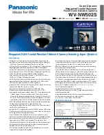
1. Secure the imager to the mounting plate, with the chamfered edge on the right
(viewed from front), using the three M5 screws provided (refer to Fig. E4).
Two sets of mounting holes are provided on the base plate to which the imager
is mounted. The holes are marked A, for use when a telescope or wide angle
lens is fitted, and B for use when no additional lenses are fitted.
2. Remove the both access covers on the enclosure (refer to Fig. E2)
3. Secure the clamping strip inside the right hand side (viewed from the front)
of the enclosure, using the two clamping nuts provided.
TI990022
Mounting Plate
Clamping Strip
Clamp
Clamping Nut
Fig. E4 Installing the Imager
4. Install the imager into the enclosure and secure with the two clamps provided.
The imager should be positioned with a gap of 1 to 2mm between the imager
lens and the front of the enclosure.
E2.1 Installing the
FTI 6
into the Environmental enclosure
To installing the imager into the Environmental enclosure:
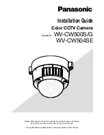
1. Secure the imager to the mounting plate, with the chamfered edge on the right
(viewed from front), using the three M5 screws provided (refer to Fig. E4).
Two sets of mounting holes are provided on the base plate to which the imager
is mounted. The holes are marked A, for use when a telescope or wide angle
lens is fitted, and B for use when no additional lenses are fitted.
2. Remove the both access covers on the enclosure
(refer to Fig. E3)
3. Secure the clamping strip inside the right hand side (viewed from the front)
of the enclosure, using the two clamping nuts provided.
TI990022
Mounting Plate
Clamping Strip
Clamp
Clamping Nut
Fig. E4 Installing the Imager
4. Install the imager into the enclosure and secure with the two clamps provided.
The imager should be positioned with a gap of 1 to 2mm between the imager
lens and the front of the enclosure.