background image

19

Section 1: Assembly and Set-Up

8/15/12

RCR3596, RCRM3596, RCR3510 & RCRM3510 Rotary Cutters   312-517M

Table of Contents

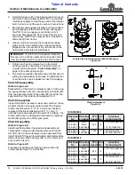
Maximum PTO Driveline Movement During Operation

Figure 1-12

Check Driveline Interference

1.

Make certain driveline yokes and safety chains are
properly attached. See steps 10 -12 on page 18.

2.

Start tractor and raise cutter up just enough to
remove support blocks. Remove support blocks.

3.

Slowly engage tractor hydraulic 3-point control lever
to lower cutter while checking for sufficient drawbar
clearance. Move drawbar ahead, aside or remove if
required.

Refer to Figure 1-12:

4.

Raise and lower implement to find maximum
extended driveline length. Check to make certain
driveline does not exceed 25

o

up or down.

5.

If needed, set tractor 3-point lift height to keep
driveline from exceeding 25

o

up.

24872

IMPORTANT: Avoid premature driveline
breakdown. A driveline that is operating must not
exceed
 an angle of 25 degrees up or down while
operating 3-Point lift.

Check Chain Assembly

Figure 1-13

Check Chains

For 3-Point & Semi-Mount Cutters

(Available through Land Pride parts department.)

Refer to Figure 1-13:

Check chains are used to control the cutting height and
allow the mower to be lowered to the same preset cutting
height effortlessly. Install lower end of check chain (#1) to
the inner hitch ear as shown in Figure 1-13, using the
3/4"-10 x 1 1/2 long bolts (#2), lock washers (#3) and
nuts (#4). Tighten securely. Install chain lugs (#5) on
either side of the tractor top link mount using pin (not
supplied). Cutting height is then set by placing proper
chain link in key slot (#5).

16264

NOTE: For additional safety in transport, raise
cutter as high as possible, and shorten check chains
to prevent inadvertent falling in transport.

Summary of Contents for 312-517M

Page 1: ...the Operator s Manual entirely When you see this symbol the subsequent instructions and warnings are serious follow without exception Your life and the lives of others depend on it Copyright 2012 Pri...

Page 2: ...3 Point Lift Type Cutter 16 Hitch Assembly 16 3 Point Hook Up 17 Driveline Installation 17 Check Driveline Collapsible Length 18 Shorten Driveline 18 Check Driveline Interference 19 Check Chains 19 C...

Page 3: ...carefully read the message that follows it In addition to design and configuration of equipment hazard control and accident prevention are dependent upon the awareness concern prudence and proper trai...

Page 4: ...hing warning lights and turn signals are recommended whenever driving on public roads Practice Safe Maintenance Understand procedure before doing work Use proper tools and equipment refer to Operator...

Page 5: ...iece of paper or cardboard NOT BODY PARTS to check for suspected leaks Wear protective gloves and safety glasses or goggles when working with hydraulic systems If an accident occurs see a doctor immed...

Page 6: ...els Order new labels from your nearest Land Pride dealer To find your nearest dealer visit our dealer locator at www landpride com 3 Some new equipment installed during repair requires safety labels t...

Page 7: ...ormation 8 15 12 RCR3596 RCRM3596 RCR3510 RCRM3510 Rotary Cutters 312 517M Table of Contents 16241 16241 818 543C Danger Guard Missing 818 552C Danger PTO Driveline ROTATING DRIVELINE KEEP AWAY 16242...

Page 8: ...rtant Safety Information RCR3596 RCRM3596 RCR3510 RCRM3510 Rotary Cutters 312 517M 8 15 12 Table of Contents 16241 16241 818 564C Chain Guard 818 142C Rotating Driveline 16241 818 556C Danger Thrown O...

Page 9: ...R3596 RCRM3596 RCR3510 RCRM3510 Rotary Cutters 312 517M Table of Contents 16241 838 094C Warning High Pressure 22296 818 540C Danger Guard Missing Do Not Operate 22296 818 552C Rotating Driveline Haza...

Page 10: ...orkers using quality materials Proper assembly maintenance and safe operating practices will help you get years of satisfactory use from the machine Application The medium duty RCR M 3596 and RCR M 35...

Page 11: ...purpose Category of hitch is dependent upon the series of cutter being used RCR3596 RCRM3596 Category l or ll hitch RCR35510 RCRM2510 Category ll or lll hitch Dealer Preparations Read and understand...

Page 12: ...your nearest Land Pride Dealer if vent plug is missing Figure 1 2 Vented Dipstick Installation Refer to Figure 1 3 Vented dipsticks are shipped loose and packaged with the Operator s Manual See your n...

Page 13: ...der bracket 4 Route hydraulic hose through loop of hose holder 9 5 Remove parking jack 10 from its storage position on the deck and attach to tongue 1 Secure with attached pin 11 Adjust jack to desire...

Page 14: ...gearbox 3 Insert driveline jackshaft 8 through the bearing support assembly 1 Pull the bearing support assembly fully against the jackshaft to extend the jackshaft splines through the bearing and out...

Page 15: ...veline 1 into pillow block bearing 9 Secure bearing support 2 with 1 2 13 x 3 1 2 bolts 3 and 1 2 flange nuts 4 NOTE Do not tighten hardware until assembly or driveline is complete 3 Install main driv...

Page 16: ...eliminate a tight or loose chain Make sure chain hook is securely locked in place NOTE May need to adjust the leveling rod nut couplers to obtain correct drawbar height Pull Type Tractor Hook Up Figur...

Page 17: ...y of the tractor that will be used a Category I tractors will have a lower hitch link hole diameter of 7 8 The top link hole diameter cutter end will be 3 4 b Category II tractors will have a lower hi...

Page 18: ...e of the inner most lugs at the rear of the cutter Secure with 3 4 bolt 3 and lock nut 4 6 Install the other clevis pin 18 flat washer 21 and cotter pin 19 into the top front hole of the A Frame 3 Poi...

Page 19: ...adjusted to allow for lateral float Please consult you tractor s manual for adjusting instructions Driveline Installation DANGER Do not engage tractor PTO while hooking up and unhooking driveline or...

Page 20: ...d tractor IMPORTANT A driveline that is too long can bottom out causing structural damage to tractor and cutter Always check driveline collapsed length during initial setup when connecting to a differ...

Page 21: ...height to keep driveline from exceeding 25o up 24872 IMPORTANT Avoid premature driveline breakdown A driveline that is operating must not exceed an angle of 25 degrees up or down while operating 3 Po...

Page 22: ...is nearby Stop blade rotation if someone is within several hundred feet Front Chain Guard RCR3510 RCRM3510 Refer to Figure 1 14 Install each front chain guard 1 with 1 2 13 x 3 1 2 long carriage bolt...

Page 23: ...someone is within several hundred feet Front Rubber Guards RCR3510 RCRM3510 Refer to Figure 1 17 Install each front rubber guard 1 and 2 with 1 2 13 x 3 1 2 long carriage bolts 3 and flange nuts 4 Fr...

Page 24: ...then loosen jam nuts 1 on both sides and rotate leveling rod adjusting nuts 2 until deck is slightly lower by an equal amounts on both sides 5 Be sure that the right and left leveling rods are equally...

Page 25: ...ft to right Some tractors have only a single adjusting lift arm 16267 Deck Leveling From Front to Rear Refer to Figure 2 4 CAUTION Avoid direct contact with cutter blades by wearing a pair of gloves C...

Page 26: ...t blade More than 1 higher off the ground than the front blade Adjust tailwheel if cutting height is too high or too low 1 Use the tractors 3 Point hydraulic control to lift the cutter such that the t...

Page 27: ...Make sure their are no hydraulic leaks on the unit Refer to Avoid High Pressure Fluids Hazard Page 3 Read and follow all Lubrication Instructions Refer to Lubrication Page 35 Make sure all gearboxes...

Page 28: ...actor PTO disengaged and all moving components completely stopped 1 Park tractor and cutter on a level surface 2 Disengage PTO place gear selector in park set park brake shut tractor off and remove sw...

Page 29: ...ve switch key Stay on tractor until blades have come to a complete stop IMPORTANT Always disengage tractor PTO before raising cutter to transport position Field Operation WARNING Clear area to be cut...

Page 30: ...ding 25 degrees up or down or at any angle that will force the driveline to bind and or hit the tractor drawbar Unhook 3 Point and Semi Mount WARNING Always disengage PTO engage parking brake shut tra...

Page 31: ...unning safety check is complete and you may shut the tractor and cutter off You should now be ready to move to the cutting site to begin mowing You should have inspected and only be cutting in an area...

Page 32: ...reak loose from the cutter at high speeds causing serious injury or death IMPORTANT Replace cutting blades with genuine Land Pride blades only Blades must be replaced in mating pairs Not replacing bot...

Page 33: ...E SPACER 24 GA 024 3 SEE LIST OF CUTTER BLADES BELOW 4 312 881H 27 x 10G OVAL DISHPAN WELDMENT 5 804 147C WASHER FLAT 1 HARD ASTMF436 6 803 170C NUT HEX TOP LOCK 1 1 8 12 PLATE Land Pride List of Cutt...

Page 34: ...to it Clutch Inspection Inspect all parts for excessive wear and condition Clean all parts that do not require replacement The original friction disc thickness is 1 8 3 2 mm and should be replaced if...

Page 35: ...ng nuts missing lug bolts wear separated rubber and bent broken or cracked wheel rims 2 Inflate air filled tires to the proper pressure Refer to Tire Inflation Chart on page 42 Refer to Figure 4 6 3 R...

Page 36: ...Clean off any dirt and grease that may have accumulated on the cutter and moving parts Scrape off compacted dirt from the bottom of deck and then wash surface thoroughly with a garden hose A coating o...

Page 37: ...side the hub casting when it is greased The hub should be greased until grease purges from the relief hole Type of Lubrication Multi purpose Grease Quantity Until grease purges from the relief hole 24...

Page 38: ...2 If oil is below bottom of plug hole add recommended gear lube through top dipstick hole until oil flows out of side plug hole Reinstall and tighten side oil plug 2 and vented dipstick 1 Type of Lub...

Page 39: ...nner tube of the driveline with a light film of grease and then reassemble Driveline U Joints Profile Shields Type of Lubrication Grease Quantity 6 pumps 13755 14618 8 Hours Driveline Profiles With Gr...

Page 40: ...ints Comer 5 5 Pints Gearbox Input Output Shaft Size Input Shaft 1 3 4 20 Spline Output Shaft 2 Dia Deck Material Thickness 10 gauge Deck Side Skirt Thickness 1 4 Skids Replaceable Stump Jumper Round...

Page 41: ...sidewalls from thrown objects Obstacle free underside Underside of deck is free of reinforcement members which tend to allow material to lodge Round back design Allows for cleaner and efficient disch...

Page 42: ...on sandy ground Raise cutting height Contacting ground frequently Raise cutting height Blades breaking Hitting solid objects Avoid hitting solid objects Blades hitting each other Blade carriers need t...

Page 43: ...8 X 1 5 220 165 350 260 485 355 3 4 16 260 190 405 295 570 420 M20 X 2 5 280 205 440 325 610 450 7 8 9 225 165 585 430 820 605 M20 X 1 5 310 230 650 480 900 665 7 8 14 250 185 640 475 905 670 M24 X 3...

Page 44: ...42 Section 8 Torque Tire Inflation Charts RCR3596 RCRM3596 RCR3510 RCRM3510 Rotary Cutters 312 517M 8 15 12 Table of Contents Tire Inflation Chart TireSize Inflation PSI AC Tire 24 x 7 7 40...

Page 45: ...altered in a way which adversely affects its performance or reliability or which has been used for a purpose for which the product is not designed Misuse also specifically includes failure to properly...

Page 46: ...Corporate Office P O Box 5060 Salina Kansas 67402 5060 USA www landpride com...

Reviews: