background image

10

Ratio Settings Table:

The table below shows the flow rate for the plain water modules and the volume of syrup dispensed after a 4 second pour, for different 

ratio settings (All at a finished drink flow rate of 60 ml/sec):

Ratio

5

5.2

5.4

5.6

5.8

6

6.2

6.4

6.6

6.8

7

Plain Water  

Flow Rate (ml/s)

50

50.32

50.63

50.91

51.18

51.43

51.67

51.89

52.11

52.31

52.50

Volume of Syrup 

(4 sec.) (ml)

40

38.71

37.50

36.36

35.29

34.29

33.33

32.43

31.58

30.77

30

Ratio

7.2

7.4

7.5

7.6

7.8

8

8.2

8.4

8.6

8.8

9

Plain Water  

Flow Rate

52.68

52.86

52.94

53.02

53.18

53.33

53.48

53.62

53.75

53.88

54

Volume of Syrup 

(4 sec.)

29.27

28.57

28.24

27.91

27.27

26.67

26.09

25.53

25

24.49

24

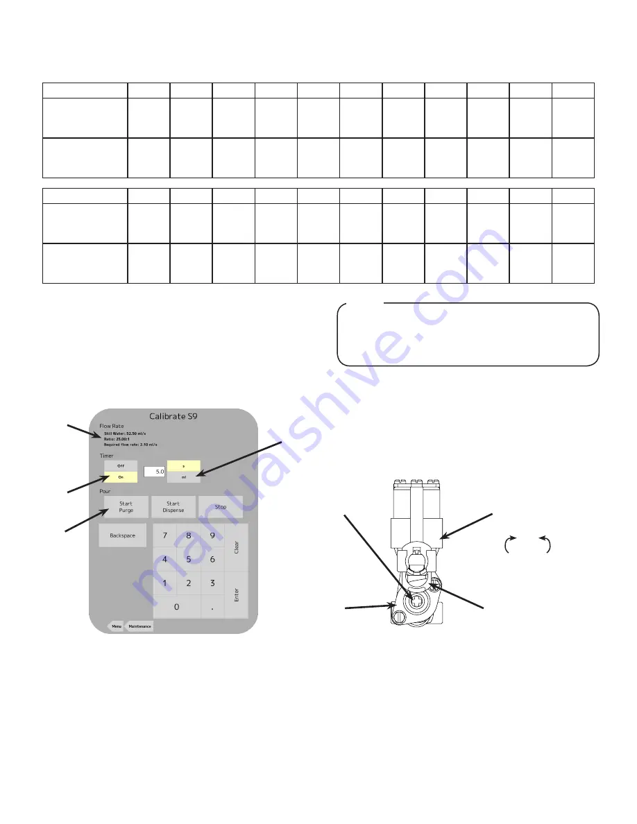
Calibrating Flavor Modules

1.  From the Maintenance menu, press the 

Calibrate

 tab on the 

far left side of the screen and press the 

Calibrate

 button for 

any designated flavor module.

2.  The water flow rate should be set from the calibration of 

the plain water module in the previous section and the ratio 

should be determined from when the flavor was configured. 

(See page 6, 

Adding New Brand/Flavor Module

)

3.  Set the Timer to the ON position and select seconds (s) as 

the desired unit of measurement.

4.  Using the keypad, enter in a time of 5 seconds as the preset 

dispensing time.   

5.  With the graduated cylinder placed in a position below the 

nozzle, press the 

Start Purge

 button. The unit will dispense 

the designated flavor for 5 seconds. 

6.  Examine the dispensed volume in the graduated cylinder. 
7.  If the dispensed volume does not match the value of 10.5 ml, 

(see note above) remove the protective cap for the  corre-

sponding valve and use a screwdriver to adjust the flavor 

flow control. 

A

B

C

D

A. Flow Rate/Ratio  C. Start Purge Button

B. Timer Icon 

   D. Unit Icon

The finished drink flow rate was set to 60 ml/sec, which 

makes the finished flavor flow rate 2.1 ml/s. In

5 seconds, the volume of syrup that should be 

dispensed is 10.5 ml. 

NOTE

8.  Repeat steps 5-7 if any more bonus flavor flow adjustment is 

necessary.

9.  Repeat steps 2-8 for any remaining bonus flavor module.
10.  Re-install top plate, splash plate, and cup rest. (See page 4)

A

B

C

D

Increase

Decrease

A. Flow Control

B. Valve Retainer 

C. Solenoid

D. Valve Body

Summary of Contents for TST

Page 1: ...that may be necessary Please read carefully the guidelines and warnings contained herein as they are intended to provide the user with essential information for the continued safe use and maintenance of the product In addition it provides GUIDANCE ONLY to the user on the correct services and site location of the unit BEFORE GETTING STARTED Each unit is tested under operating conditions and is thor...

Page 2: ...mm WEIGHT Shipping 40 lbs 18 14 kg Operating 35 lbs 15 88 kg CARBON DIOXIDE CO2 SUPPLY Min Pressure 70 psi 0 483 MPa Max Pressure 80 psi 0 552 MPa FITTINGS Carb Water Inlet 3 8 inch 9 5 mm barb Carb Water Outlet 3 8 inch 9 5 mm barb Plain Water Inlet 3 8 inch 9 5 mm barb Brand Syrup Inlets 3 8 inch 9 5 mm barb Drain Fitting 5 8 inch 15 9 mm barb ELECTRICAL 24 VDC 2 0 Amps FLOW RATE 1 5 2 0 ounces ...

Page 3: ...Design states that the maximum reach height from the floor should be no more than 48 in 1 2 m if touch point is less than 10 in 254 mm from the front of the counter or a maximum of 46 in 1 17 m if the touch point is more than 10 in 254 mm and less than 27 in 685 mm from the front of the counter For more information about the customer s legal requirements for the accessibility of installed equipmen...

Page 4: ...ee the manufacturer s specifications and instructions for installation The following are the instructions for plumbing the remote chiller system to the tower NOTE A Nozzle A 3 Remove the splash plate 4 Turn on the water supply 5 Verify all Bag in Box contain syrup and check for leaks 6 Open the pressure relief valve located on the remote chiller system by flipping up on the valve cap lever Hold op...

Page 5: ...then hold your finger to the screen for a minimum of two 2 seconds Slide Finger to Left and Hold 13 A keypad will appear enter the designated pin number to access the service menu Contact Lancer Technical Support for the units designated pin number NOTE Enter Designated PIN 14 For manager s access to the service menu press and hold the upper right hand corner of the screen for a minimum of five 5 ...

Page 6: ... remote chiller 25 Purge the carbonated water module again until a steady flow of carbonated water is achieved 26 Purge each syrup module until a steady flow of syrup is achieved A Purge Tab B Up to 4 Purge Buttons Selected C Grayed Out Purge Button A B C 18 Press the Purge tab on the far left side of the screen 19 Press the Purge buttons for both the plain water and the carbonated water modules A...

Page 7: ...does not set the ratio for the finished drink Adjust the ratio by selecting the Ice or No Ice ratio using the buttons in the upper right corner of the screen or by manually adjusting the ratio by tapping the number and entering the new value on the keypad NOTE 10 Once a brand flavor has been selected to a corresponding module press the Valve Configuration button to return to the Valve Configuratio...

Page 8: ...ated cylinder being used to calibrate the plain water module The larger the volume dispensed the more accurate the results Use the example 150 ml 7 With the graduated cylinder placed in a position below the nozzle press the Start Purge button The unit will dispense the volume designated in the previous step A Graduated Cylinder B Nozzle A B 8 Examine the dispensed volume in the graduated cylinder ...

Page 9: ...Flavor Module The refrigeration unit should have been running for at least one 1 hour before attempting to set flow rates on valves The drink temperature should be no higher than 40 F 4 4 C when flow rates are set This is best done after the remote chiller has already made an ice bank If applicable NOTE The brand syrup modules can be calibrated the same as the plain water module by using volume ml...

Page 10: ...ed from when the flavor was configured See page 6 Adding New Brand Flavor Module 3 Set the Timer to the ON position and select seconds s as the desired unit of measurement 4 Using the keypad enter in a time of 5 seconds as the preset dispensing time 5 With the graduated cylinder placed in a position below the nozzle press the Start Purge button The unit will dispense the designated flavor for 5 se...

Page 11: ...unit using the appropriate procedures outlined in the Cleaning and Sanitizing section of this manual Every Six Months Clean remote chiller according to manufacturer s instructions if necessary Clean the entire exterior of the unit The following are the features only available from the manager s access to the service menu PIN 6655 see page 5 For information on more available features see the TsT Us...

Page 12: ... is dispensing and when the unit is not dispensing Idle 3 Below the Nozzle Light sliders the user can change how the ribbon lights on the side of the dispenser are displayed Spectrum Ribbon lights cycle through preset colors The brightness and the speed at which the colors cycle can be adjusted using the sliders One Color Ribbon lights are displayed using only one color determined by the user Pres...

Page 13: ...pment must provide continuous maintenance as required by this manual and or state and local health department guidelines to ensure proper operation and sanitation requirements are maintained The cleaning procedures provided herein pertain to the Lancer equipment identified by this manual If other equipment is being cleaned follow the guidelines established by the manufacturer for that equipment Cl...

Page 14: ...itizer Let sit for ten 10 minutes 10 Reconnect product lines to BIB s and draw drinks to flush solution from the dispenser 11 Taste the drink to verify that there is no off taste If off taste is found flush product system again Following sanitation rinse with end use product until there is no aftertaste Do not use a fresh water rinse This is a NSF requirement Residual sanitizing solution left in t...

Page 15: ...15 Counter Cut out To Scale 1 62 41 28 5 02 127 49 4 13 101 71 6 19 157 30 CUT ALONG DOTTED LINES FRONT OF UNIT ...

Page 16: ...agram S1 S7 S3 S8 S4 SD PW S9 S5 RC S2 S10 S6 S1 SD PW S3 S4 S5 S6 S7 S8 S9 S10 S2 Item Description S1 Syrup Line 1 S2 Syrup Line 2 S3 Syrup Line 3 S4 Syrup Line 4 S5 Syrup Line 5 S6 Syrup Line 6 S7 Syrup Line 7 S8 Syrup Line 8 S9 Syrup Line 9 S10 Syrup Line 10 PW Plain Water Line SD Soda Line RC Recirculation Line ...

Reviews: