21
Call 1-888-370-6531 for Technical Support
Procedure for Heat Exchanger Cleaning:
1.
If heater is hot, allow it to cool before cleaning. Wear all safety
equipment.
2. Unplug the black burner cord at the cabinet wiring box and the red plug on the grey cable
from the side of the burner.
3. Disconnect the fuel tubing by loosening the flare fitting attached to the elbow on the side of
the burner. Hold the elbow with the ½” wrench and turn the flare fitting with the ¾” wrench.
Have a rag ready, as some oil will drip. Cap the elbow to prevent additional oil leaking out.
4. Remove the four ½” nuts holding the burner to the cabinet, and lift the burner out of the
cabinet. Set it aside.
5. Scrape the combustion chamber sides and gently tap the flue pipe. Allow ash to fall to the
bottom of the heat exchanger.
6. Remove the safety covers over each clean out port by removing the two screws.
7. Remove the two screws securing each port cap (located on opposing sides, near the
bottom of the heater cabinet) and remove both caps. Be prepared to catch/contain any
ash that may spill out as the caps are removed.
8. Tape a trash bag to one opening with duct tape, so that ash can fall into the bag, and
use a cleaning tool or brush to push ash into the bag from the opposite opening. A shop
vacuum with a HEPA filter may also be used to remove ash.
9. Remove the trash bag and properly dispose of the ash.
10. Remove the viewport cover and glass by unscrewing the cover from the viewport tube.
11. Clean with glass cleaner. If glass cleaner is not effective, carefully scrape the glass with a
razor blade.
12. Reinstall the viewport glass (with gaskets) and cover. Do not overtighten.
13. Inspect the cleaned heat exchanger and flue. If damaged, call for Technical Support.
14. Inspect the cap-insulation gaskets. If damaged, replace the gaskets (PN 76001183).
15. Reinstall the port caps, ensuring that the baffle is on the same side of the heater as the
air louver. Use existing screw holes and replace screws if they are damaged.
16. Reattach the safety covers.
17. Reinstall the burner, making sure the grey cord with the red plug is out of the way.
Replace the burner gasket if damaged (PN 20910103). Install the nuts holding the
burner to the cabinet.
18. Connect the flare fitting on the fuel tubing to the elbow on the side of the burner.
19. Plug in the black burner cord at the cabinet wiring box, making sure to align the key
and slot, and the red plug on the side of the burner.
20. Turn on power to the heater and wait 10 minutes before trying to fire it back up to allow
the oil to heat up.
21. Restart the heater per the procedure in Section 5.4.2.
Make sure to perform startup (5.4.2) and system checks (5.4.3) after every
maintenance cycle. Record maintenance performed in the log.
Summary of Contents for MX 75
Page 2: ......
Page 41: ...8 Appendices 8 1 Wiring Diagram ...
Page 42: ......
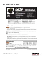
Page 43: ...34 Call 1 888 370 6531 for Technical Support 8 2 Primary Control Instructions ...
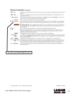
Page 44: ...35 Call 1 888 370 6531 for Technical Support Not used with RES 75 kBTU h units ...
Page 45: ...36 Call 1 888 370 6531 for Technical Support No latch up with RES 75 kBTU h units ...
Page 46: ...37 Call 1 888 370 6531 for Technical Support ...
Page 54: ...45 Call 1 888 370 6531 for Technical Support 9 ...


