background image

1 About this operating manual 

Issue EN 2022/05     PUK 6     Operating manual 

8/56 

1.3


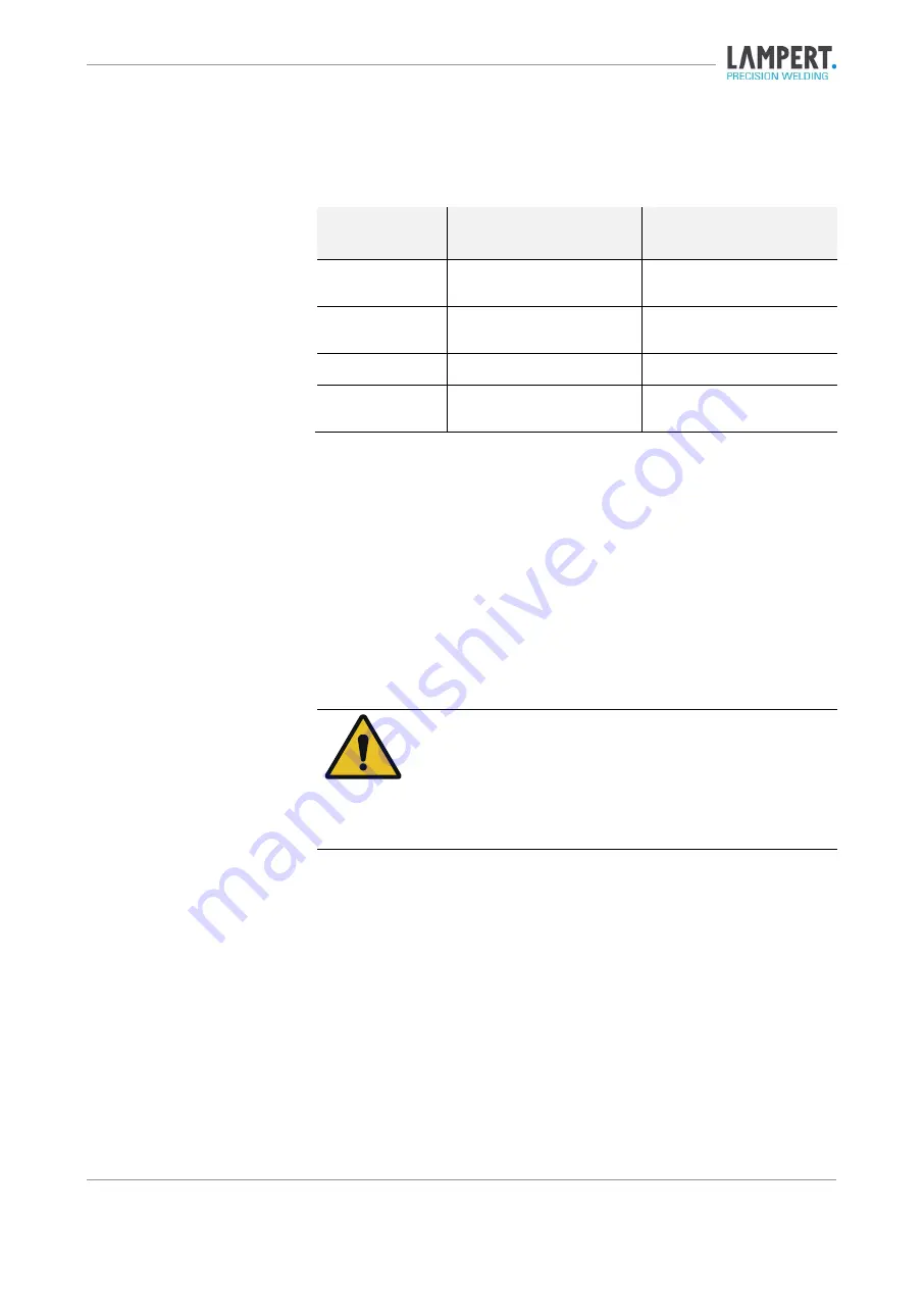
Structure of the warnings 

Signal word 

Avoidance of ... 

Possible consequences if 

the warning is not heeded: 

DANGER 

Personal injury  

(imminent danger) 

Death or severe injuries! 

WARNING 

Personal injury  

(potentially hazardous situation) 

Death or severe injuries! 

CAUTION 

Personal injury 

Light or minor injuries! 

NOTE 

Property damage 

Damage to the device or its im-

mediate surroundings! 

Tab. 1.1 Warning levels 

The warnings are structured as follows: 


Warning sign with signal word in accordance with the warning level 

(see Tab 1.1)  


Type of hazard (description of the hazard) 


Consequences of the hazard (description of the consequences of the 

hazard) 


Hazard prevention (measures to prevent the hazard) 


DANGER! 
Type of hazard 

Consequences of hazard 


Hazard prevention 


Summary of Contents for PUK 6

Page 1: ...OPERATING MANUAL PUK 6 Lampert Werktechnik GmbH Fine welding device Issue EN 2022 05 ...

Page 2: ...vice Type PUK 6 Manufacturer Lampert Werktechnik GmbH Ettlebener Strasse 27 97440 Werneck Telefon 49 0 9722 94 59 0 Telefax 49 0 9722 94 59 100 E Mail mail lampert info Website www lampert info Revision index Date of revision ...

Page 3: ...suse 11 2 4 Safety instructions 11 General information 11 Personal protective equipment 11 Handling protective gas cylinders 12 During transport 12 During installation 12 During commissioning 12 During operation 13 Maintenance and inspection work 13 During disassembly 14 2 5 Residual risks for device operation 14 2 6 Selection and qualification of personnel 14 2 7 Safety devices 15 2 8 Safety sign...

Page 4: ...5 1 Setting up the device 29 5 2 Establishing supplies 29 5 3 Connect eye protection 30 5 4 Insert the electrode into the handpiece 30 5 5 Adjusting the electrode length 31 5 6 Connecting the handpiece 32 5 7 Connecting the contact clamp 32 5 8 Connecting optional accessories 32 6 Graphical user interface 33 6 1 Main menu 33 Material selection 34 Welding power and pulse duration 35 Menu bar 37 Geo...

Page 5: ...sic information and tips 47 8 Help with faults 48 9 Care and inspection work 49 9 1 Care and inspection schedule 49 9 2 Carry out care and inspection work 49 Cleaning the PUK 6 49 Regrinding electrodes 49 10 Disposal and recycling 50 11 Dimensions and technical data 51 11 1 Device dimensions 51 11 2 Technical data for the device 52 12 Appendix 53 12 1 Service address 53 12 2 Spare and wear parts 5...

Page 6: ...tions must Be fully read and applied by any person assigned to work on the device Be stored in such a way that they are accessible at all times to all users at the place of use of the device Be handed over to third parties together with all necessary documents when the device is passed on Observance of the operating instructions helps Avoiding dangers Reduce repair costs and downtime Increase the ...

Page 7: ... operating instructions handling instructions are marked with the following symbols The steps marked with this activity symbol may be carried out in any or der 1 Numbered steps must be carried out exactly in the given order The result symbol describes the result or intermediate result of an ac tion Application tip The TIP indicates additional information for easy and safe use of the de vice TIP No...

Page 8: ... or severe injuries CAUTION Personal injury Light or minor injuries NOTE Property damage Damage to the device or its im mediate surroundings Tab 1 1 Warning levels The warnings are structured as follows Warning sign with signal word in accordance with the warning level see Tab 1 1 Type of hazard description of the hazard Consequences of the hazard description of the consequences of the hazard Haza...

Page 9: ...ntifiable source of danger it is preceded by one of the following pictograms Electrical voltage Warning of possible electric shock potentially with fatal conse quences Hand injuries Warning about the danger of hand injuries Hot surfaces Warning of hot surfaces Pressurised containers Warning of fire and explosion hazard Optical radiation Warning of optical radiation Hazard due to electromagnetic ra...

Page 10: ...following of all instructions in the operating manual The complete reading and following of all safety and hazard instructions Compliance with maintenance and servicing work The device is designed for use in industrial and commercial applications The manufacturer is not liable for damage resulting from use outside this area of application Temperature range of the ambient air during operation 10 C ...

Page 11: ...shielding gas Exerting too much pressure on the electrode Use of the device without personal protective equipment 2 4 Safety instructions General information If the device shows signs of damage it must be taken out of service If malfunctions occur the device must be taken out of service Personal protective equipment The personal protective equipment listed below must be worn during every welding o...

Page 12: ...ced on a non combustible surface During commissioning The device must not be connected to a circuit in which devices e g TIG welders that work with high frequency are operated at the same time This may cause irreparable damage to the device In the case of simul taneous operation with equipment that operates at high frequency al ways ensure that the device is operated on a separate individually fus...

Page 13: ...on weld ing has been completed In normal welding operation always make sure that the contact clamp for fixation welding is not connected to the device An extraction system must be installed at the workplace In addition the workplace should be sufficiently ventilated without creating draughts The flow rate at the flow regulator must be between 2 3 litres minute Maintenance and inspection work Disco...

Page 14: ...tive gas cylinders Eye and skin damaging arc radiation on uncovered skin areas 2 6 Selection and qualification of personnel The operator undertakes to only allow persons to work on the device who Are familiar with the basic regulations on occupational safety and acci dent prevention and have been instructed in the handling of the device Have read and understood this operating manual in particular ...

Page 15: ... that they have read and understood this op erating manual and in particular the chapter on safety instructions and that they will observe this information 2 7 Safety devices The device has a thermal cut off device that is activated if the heat build up is too high preventing the device from overheating ...

Page 16: ...fety signs Fig 2 1 Safety signs on the back of the device Safety sign Description Electromagnetic fields may impair the function of pacemak ers Inhaling welding fumes can endanger your health Arcs can damage the eyes and injure the skin Welding sparks may cause an explosion or fire ...

Page 17: ...ified electrician needs to open the device the main cable always needs to be unplugged before The union nut of the protective gas hose may only be tight ened by hand on the protective gas connection The use of tools e g wrenches can damage the protective gas con nection Tab 2 1 Safety sign ...

Page 18: ...sly monitored and the target parameters are adjusted as required using control algorithms The energy pulses generated by the power source are transferred to the workpiece via the handpiece included in the scope of delivery and its elec trode thereby carrying out the welding process Scope of delivery The scope of delivery of the device includes Handpiece with connection cable Main cable 3 m gas con...

Page 19: ...Structure and function 3 Issue EN 2022 05 PUK 6 Operating manual 19 56 3 2 General overview Fig 3 1 Overview of PUK 6 with handpiece 1 PUK 6 2 Handpiece with connection cable 2 1 ...

Page 20: ...cket for the welding handpiece 5 Socket for contacting tools spot welding Displays the user interface of the operating software The Turn push controller can be turned tilted and pressed Depending on the software dialogue the following actions can be triggered Turn Changing the welding parameters or the operating mode Tilt Navigating the user interface Press Confirm the selected choice Display Turn...

Page 21: ...ting manual 21 56 For connecting contact elements for fixation welding For connecting the handpiece For connecting contact elements such as welding table contact terminals or clamps Socket for contacting tools Handpiece socket Socket for contacting tools ...

Page 22: ...onnection 5 Mains switch 6 Fuse compartment 7 IEC 60320 C14 socket 8 Protective gas connection 9 Mains voltage approved for this device 10 Ventilation opening 11 Connection socket for foot switch 12 Connection socket for electrode grinding motor 13 Hazard warnings 14 Connection socket for eye protection system 1 9 5 8 2 3 4 7 6 10 11 12 13 14 9 ...

Page 23: ...4 bar The ventilation opening is used for air circulation and cooling of heat sensi tive electronic components inside the device The permissible mains voltage for the device is marked with a red dot shaped marking and must not be exceeded A foot switch with M12 connection can be connected to this socket A Lampert electrode grinding motor from the accessories range can be con nected to this socket ...

Page 24: ...r The hand piece can be guided freely appropriate eye protection required or clamped in a corresponding device e g handpiece holding arm of a Lampert welding microscope The nozzle with ceramic insert ensures the targeted gas supply at the welding location The connection cable contains both the cable guide for the power transmis sion and the hose for the gas supply to the handpiece The handpiece co...

Page 25: ...he diamond grinding wheel is used for grinding the electrodes and can be replaced if it shows signs of wear after prolonged use The electrode grinding motor housing consists of a housing with guide holes 15 angle Ø 0 5 0 6 0 8 1 0 mm and an on off button The connection cable is screwed with the M12 plug to the corresponding socket on the rear of the welding device housing Diamond grinding wheel wi...

Page 26: ...process can alternatively be triggered by pressing the foot switch When the foot switch is active automatic triggering by electrical contact workpiece contact is deactivated When the fixation welding mode is selected the foot switch is permanently activated The foot switch connection cable with M12 plug is screwed to the back of the welding device Foot switch Connection cable with M12 plug 1 2 ...

Page 27: ...ng voltage 7 Standardised operating current 8 Maximum rated value of the mains current 9 RMS value of the largest mains current 10 Protection type 11 Keep away from precipitation 12 Mains circuit rated frequency 13 Maximum rated welding current at 20 C ambient temperature 14 No load peak value 15 Symbol for the welding process Tungsten inert gas welding here 16 Symbol for the welding current DC he...

Page 28: ... recommend packing the device in the original box or a similar suitable con tainer To avoid scratches or damage to the surface it is also advisable to line transport containers with soft dry and scratch free materials e g foam 4 2 Storage For longer storage disconnect the mains plug and cut off the gas supply The storage location of the device must be dry and dust free and must not be subject to e...

Page 29: ... placed on a level maximum angle of inclination 10 stable and insulated surface 5 2 Establishing supplies Plug the mains cable with the mains plug into the mains socket on the back of the device Then plug the mains plug into a socket with a suitable mains voltage WARNING Pressurised containers Fire and explosion hazard Check the tightness of gas cylinders and supply lines Fasten the appropriate fl...

Page 30: ...nto operation The performance of this functional test is explained in more detail in chapter 7 3 5 4 Insert the electrode into the handpiece Fig 5 1 Handpiece components 1 Argon nozzle 2 Tungsten electrode 3 Clamping nut with collet 4 Handpiece housing The argon nozzle with ceramic insert ensures the targeted gas supply at the welding location The tungsten electrode is used to make electrical cont...

Page 31: ... and remove the used tung sten electrode if necessary 4 If a different electrode diameter is to be used the collet chuck might also have to be changed accordingly To do this completely loosen and remove the clamping nut and then pull the collet out and insert a match ing collet Screw the clamping nut back on Insert the new tungsten electrode into the collet and adjust to the correct length If you ...

Page 32: ...onnector hand tight as far as the thread will allow This is important to ensure proper electrical contact and that no gas can escape from the system 5 7 Connecting the contact clamp Insert the black contact clamp supplied into the left socket marked plus 5 8 Connecting optional accessories The optional accessories e g grinding motor or foot switch are connected via the M12 plug attached to the con...

Page 33: ... the welding parameters Displaying recommended welding parameters Selecting different operating levels or functions Performing test functions Showing error messages 6 1 Main menu Fig 6 1 Main menu 1 Material selection 2 Menu bar 3 Foot switch activated optional 4 Geometry selection 5 Pulse duration in milliseconds 6 Speed levels 7 Welding power in percent 4 2 3 1 7 6 5 ...

Page 34: ...terial selection Here you select the material to be processed The following materials are available for selection Abbreviation Material designation Uni Universal Au Gold Ag Silver Pt Platinum Pd Palladium CuSn Bronze V2A Stainless steel Ti Titanium Sn Tin CuZn Brass Cu Copper Tab 6 1 Material selection ...

Page 35: ...d by pressing the connected foot switch for a longer time approx 3 seconds The blue foot symbol on the display indi cates that the foot switch is ready for operation The welding process can now be triggered directly via the foot switch In foot switch mode the con tact of the workpiece with the tungsten electrode is signalled by periodic dimming of the eye protection system The red range indicates ...

Page 36: ...ended in special material and geometry related applications Otherwise there is a risk of inhomogeneous welds The use of higher welding powers in the red range is therefore only recom mended for experienced users TIP For fine welding it is recommended to start with a lower weld ing power of approx 20 with a very short pulse duration and to work up to the correct value by small changes of the weld i...

Page 37: ...al energy introduced into the workpiece is always made up of both set parameters these must be selected before a weld after a detailed analysis of the welding task the material and the workpiece geometry Menu bar The menu bar can be used to switch to the various menu and setting levels Fig 6 4 Menu bar The menu bar consists of the following menu levels 1 Main menu 2 Micro mode 3 Fixation mode 4 Se...

Page 38: ...thinner than ca 0 3 mm This setting offers very low development of heat especially for short weld ing times 0 3 mm Welding in sharp angles and tight joint situations Here it is IMPORTANT to use short welding times Melting of welding wire Use identical alloy wire with a diameter of ca 0 4 mm Application of welding wire on claws and stone settings Particularly low energy melting of thin welding wire...

Page 39: ...umerous ap plications and is automatically preselected in most welding functions The fast welding cycle speed mode enables faster work and prevents ex cessive cooling of the workpiece between the welding points A faster weld ing cycle therefore results in a higher heat input into the workpiece 6 2 Micro mode Fig 6 6 Micro mode Micro mode is suitable for particularly sensitive materials and thin ma...

Page 40: ...fixation mode is left the cable must be removed again to prevent erroneous welding Connect both of the workpieces which are to be fixed to an area of bare metal using a contact clamp one to the blue one and the other to the black When the two workpieces are touching the welding process can be trig gered using the foot switch The hand piece is not used during this process The required welding power...

Page 41: ... push control Here the eye protection filter is activated and thus darkened With this func tion the Lampert eye protection system can be checked for correct function Here the gas valve in the device is opened This function is used to be able to set the gas flow correctly on the flow controller recommended gas flow 2 3 l min Here the welding tone to announce the start of the welding process is acti...

Page 42: ...back of the device 5 In the settings menu select the update button with the rotary push con trol and confirm 6 An update window opens as shown in Fig 6 9 The update can be started with the Start Update button The progress of the update is shown in percent on the display 7 The device restarts after the update 8 You can check whether the software version has been updated correctly in the update menu...

Page 43: ...elding for a short period The settings are saved and no uncontrolled welds are possible This means you do not have to switch off the device between two consecu tive applications If you do not use the device for more than one hour between two applica tions we always recommend that you switch the device off completely us ing the mains switch for optimum energy consumption ...

Page 44: ... the control dial Now the gas flow can be adjusted to a value between 2 and 3 litres mi nute by turning the flow regulator clockwise Please also refer to the separate operating instructions for the flow regulator After setting the correct flow rate close the gas valve by pressing the control knob again The gas flow is now set correctly 7 2 Switching on the PUK 6 CAUTION Danger due to operating err...

Page 45: ... the device If use is possible clarify the required minimum distance in advance and do infringe upon this distance at any time when working with the de vice Proceed as follows 1 Make sure that the mains cable is connected to the device and the socket 2 Check the gas connection and carefully open the gas cylinder valve 3 Set the power switch to I 4 Read the safety instruction on the display and con...

Page 46: ...the workpiece and the electrode The welding process now starts automatically 8 Do not release the contact between the workpiece and the electrode until the welding process is finished 9 By touching the workpiece again you can trigger the next welding pro cess The fine welding device is equipped with a function to prevent the electrode becoming welded to the workpiece by incorrectly pressing or pre...

Page 47: ...nal of the connecting cable or via a contacting tool at a metallically bright point Free hand welding leads to poorer welding results due to uncontrollable movements of the hands The pressure on the electrode tip should only be light A gas flow rate of approx 2 3 liters minute is recommended The gas flow should be checked regularly at the flow controller and readjusted if necessary The angle at wh...

Page 48: ... 4 6 5 Poor ignition characteristics Electrode clamped loosely in hand piece Tighten the clamping nut on the hand piece by hand 6 Oxidation and rusting Excessive gas pressure Reduce flow rate ca 2 l min 7 Severe oxidation of the weld ing points Incorrect shielding gas Use inert shielding gas e g Argon 4 6 8 Tungsten embedded in base material Excessive pressure of the electrodes on the workpiece To...

Page 49: ... reground Replace electrode when worn out Tab 9 1 Care and inspection schedule 9 2 Carry out care and inspection work Cleaning the PUK 6 Use a dry slightly damp cloth to remove dust and carefully clean the surfaces of the device A non abrasive glass cleaner e g spectacles cleaner can be used for the screen on the front of the display Regrinding electrodes 1 Switch off the device 2 Remove the elect...

Page 50: ...arded devices unusable by removing the mains cable Only for EU countries In accordance with European directive 2012 19 EU regarding the disposal of used electrical and electronic equipment discarded electri cal devices must be separated and collected and sent for recovery in an en vironmentally friendly manner ...

Page 51: ...hnical data 11 Issue EN 2022 05 PUK 6 Operating manual 51 56 11 Dimensions and technical data 11 1 Device dimensions Name Value Unit Earth 9 5 kg Earth Length 365 mm Width 190 mm Height 305 mm Tab 11 1 Machine dimensions ...

Page 52: ...or Tripping characteristics B Power consumption 1000 W Max current strength 4 4 A Breaking capacity 6 kA Protection class per EN 61140 2016 Protection class I General data Max operating temperature 60 C Max outside temperature Transport storage 20 55 C Operation 10 40 C Relative humidity Up to 50 at 40 C Up to 90 at 20 C Max location altitude above sea level 1000 m Protection type per EN 60529 201...

Page 53: ...vice In the event that you have not purchased the device via an authorised Lam pert partner company or are unable to locate one please contact the manu facturer directly Lampert Werktechnik GmbH Ettlebener Strasse 27 97440 Werneck Germany 49 9722 9459 0 mail lampert info 12 2 Spare and wear parts Only original spare and wear parts may be used for your PUK 6 These are listed in the Lampert spare pa...

Page 54: ...12 Appendix Issue EN 2022 05 PUK 6 Operating manual 54 56 12 3 CE conformity ...

Page 55: ...Appendix 12 Issue EN 2022 05 PUK 6 Operating manual 55 56 ...

Page 56: ...ior notice We would like to point out that these operating instructions may only be reproduced for internal pur poses and that their contents must remain unchanged The content may not be made available to third parties and may not be used for purposes other than those for which it was intended Copyright remains with Lampert Werktechnik GmbH Lampert Werktechnik GmbH Ettlebener Strasse 27 D 97440 We...

Reviews: