59
The boiler must be installed and function outdoors.
For installation use only original LAMBORGHINI parts.
FLUE EXHAUST TYPES
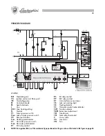
DOUBLE PIPE OUTLET KIT
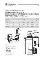
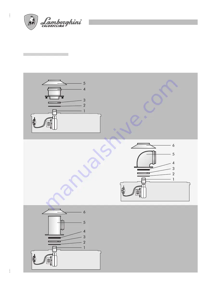
To install the double pipe kit insert the funnel
1
(supplied with the boiler) in the fan. Insert the
diaphragm
3
between the adhesive seal
2
and the 5
mm spacer
4
. Fix the double pipe flue exhaust
5
with
the screws and insert the supplied silicon hood
6
.
The latter must rest on the upper part of the boiler to
prevent water infiltrating.
Warning:The boiler can only be fitted with
the high double pipe flue exhaust
kit.
CONCENTRIC FLUE EXHAUST KIT
To install the concentric kit insert the funnel
1
(supplied
with the boiler) in the fan. Insert the diaphragm
3
between the adhesive seal
2
and the 5 mm spacer
4
.
Fix the bend
5
with the screws and insert the supplied
silicon hood
6
. The latter must rest on the upper part
of the boiler to prevent water infiltrating.
FAN-FORCED DRAUGHT FLUE EXHAUST KIT
To install the forced draught kit insert the funnel
1
(supplied with the boiler) in the fan. Insert the
diaphragm
3
and the adhesive seal
2
. Fix the flanged
section
4
with the screws and insert the silicon hood
5
. The latter must rest on the upper part of the boiler
to prevent water infiltrating.
78
INSTALACIÓN Y PUESTA EN FUNCIONAMIENTO
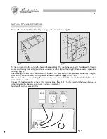
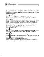
Quite la base del termostato programador haciendo palanca sobre los dos ganchos inferiores (
fig. 1
)
Sujete a la pared el termostato programador a 1,5 metros del suelo, utilizando los orificios de la base, en un
lugar lejos de la puerta de entrada, de las ventanas, o de fuentes de calor que puedan influir en la tempera-
tura ambiente (
fig. 2
).
Tras haber controlado que la caldera no esté encendida, efectúe la conexión eléctrica del programador
utilizando un cable bipolar, evitando que los cables pasen por el mismo sitio que los cables de red.
Si esto no fuera posible, utilice un cable de conductores encerrados cuyo conductor debe conectarse a la
instalación de puesta a tierra.
Conecte los extremos del cable a la regleta de bornes “-IN+” (
fig. 3
), respetando tajantemente las polaridades
indicadas (el + de la caldera al + del termostato programador; el - de la caldera al - del termostato programador).
El cable tiene que tener un largo máximo de 50 m.
fig. 3
CALDERA
ACTIVACIÓN
PROGRAMADOR
SONDA
EXTERIOR
+ CALDERA
- CALDERA
fig. 1
fig. 2
Summary of Contents for thin 24 MCS W TOP U/IT
Page 3: ......
Page 5: ......
Page 7: ......
Page 9: ......
Page 11: ......
Page 13: ......
Page 15: ......
Page 17: ......
Page 19: ......
Page 21: ......
Page 23: ......
Page 25: ......
Page 27: ......
Page 29: ......
Page 31: ......
Page 33: ......
Page 35: ......
Page 37: ......
Page 39: ......
Page 41: ......
Page 43: ......
Page 45: ......
Page 47: ......

