50
●
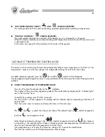
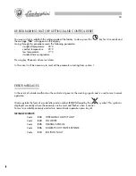
COPYING HOURLY PROGRAMMING
To speed up programming, you can “paste” the settings for a specific day onto another day.
Press
V
to select the day from which you wish to copy the settings.
Press the
Copy
key within 5 seconds to copy and then press the
+
and
–
keys to select the page onto which
you intend to “paste” them (the “destination” day is indicated by a flashing
indicator).
Press
P
to paste and memorise the settings or
V
to cancel.
●
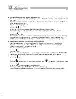
TEMPORARY TEMPERATURE VARIATION
It is possible to vary set room temperature during automatic temperature control mode by acting on the
+
and
–
keys. Variations will be shown on the display.
When this function is used the symbol indicating the present level goes out and the indicator light corresponding
to the relevant time slot starts flashing.
The new temperature will remain operative until the next value change, after which the programme will revert
to normal settings.
NOTE:
Immediately after setting the date and the day (section 2) a factory-set default programme is activated.
This programme is given in the table below.
Standard Programme
from Monday to Friday
Saturday and Sunday
Low temp.
23:00+06:00
23:00+08:00
Comfort temp.
06:00+09:00
08:00+23:00
Low temp.
09:00+17:00
Comfort temp.
17:00+23:00
“MANUAL” TEMPERATURE CONTROL MODE
Pressing the
key enables manual operation of temperature control.
When manual mode is selected the
symbol appears on the display.
This mode excludes the daily/weekly timer and adjusts rooms temperature according to a standardised tem-
perature setting (modified by pressing
+
or
-
).
87
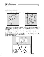
CONEXIÓN HIDRÁULICA
Una vez colocados los ganchos de sujeción metan la plantilla de montaje y apóyenla contra la pared; después
de haber fijado las uniones terminales montadas previamente en la plantilla, procedan a poner todas las
tuberías: ida instalación, retorno instalación, agua fría, agua caliente, y eventualmente también las de gas y
alimentación de la línea eléctrica con termostato ambiente.
Una vez puestas las tuberías se pueden desenroscar las uniones terminales y meter tapones normales cerrados
para pasar a la prueba hidráulica de la instalación. La plantilla la podemos dejar o quitar, ya que después de
las operaciones de acabado de la pared (enlucido o azulejos), quedará completamente cubierta; se verán
sólo fuera de la pared terminada los dos ganchos de sujeción, y quedará una apertura que corresponderá
con los empalmes. A continuación pongan la caldera sobre los dos ganchos de sujeción mediante los agujeros
correspondientes en la parte posterior del armazón, apóyenla completamente contra la pared y fijen las
tuercas de inmovilización en los ganchos.
Por último efectúen la conexión hidráulica mediante los tubos que se dan con el equipamiento base, cortándolos
a medida, según la distancia que haya entre las juntas de la caldera y las de la plantilla colocadas en la
pared.
DESCRIPCIÓN
C
Agua caliente Ø 1/2"
G
Gas Ø 3/4” ( Véase grifo en
dotación )
F
Agua alimentación caldera Ø
1/2" (Fría)
AE
Alimentación eléctrica
M
Ida instalación Ø 3/4"
R
Retorno instalación Ø 3/4"
GS
Ganchos de sujeción Ø 10 mm
NOTA:
Preparar piezas
hidráulicas de unión
hembra
Summary of Contents for thin 24 MCS W TOP U/IT
Page 3: ......
Page 5: ......
Page 7: ......
Page 9: ......
Page 11: ......
Page 13: ......
Page 15: ......
Page 17: ......
Page 19: ......
Page 21: ......
Page 23: ......
Page 25: ......
Page 27: ......
Page 29: ......
Page 31: ......
Page 33: ......
Page 35: ......
Page 37: ......
Page 39: ......
Page 41: ......
Page 43: ......
Page 45: ......
Page 47: ......


