41
LED 24MB W TOP-U/I
LED 24MBS W TOP-U/I
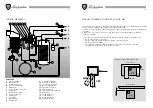
LEGEND
1
Thermohydrometer
2
Clock (optional)
3
Heating thermostat
4
Summer/winter selector
5
Sanitary thermostat
6
Release button
7
Heating circulator
MAIN COMPONENTS
8
Hot water cylinder
9
Hot water cylinder circulator
10
Sanitary expansion tank
11
Safety valve
12
Expansion tank
13
Draught diverter
14
Flue control
WILO
NO WATER
ALARM
WILO
1
2
3
4
5
6
1
2
3
4
5
6
7
8
9
10
11
12
13
14
15
16
17
7
8
9
10
11
12
18
19
15
16
17
20
NO WATER
ALARM
1009DIS1056
15
Exchanger
16
Burner
17
Gas valve
18
Fan
19
Sealed chamber hood
20
Flue gas pressure switch
88
N L TR N
OFF
ON
CM2
B/P
Met.
CM1
P1
P2
36 37
1009DIS1064
4
1
2
3
5
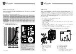
DESCRIPCIÓN
A
Tornillo de regulación potencia máxima
B
Tuerca de inmovilización bloqueo regulación
C
Muelle
D
Tornillo de regulación potencia mínima
E
Bobina
F
Muelle de fijación
G
Tornillo de regulación piloto
1
Regulación encendido lento
2
Regulación potencia instalación
3
Puente B/P GAS NATURAL
4
Puente limitación encendidos
5
Puente para calefacción de pavimento
Cor tando el puente 5 la caldera se
autorregula a una temperatura máxima de
calefacción de 40
°
C.
I
H
1009DIS1050
Diafragma gas
Empaquetadura
Válvula gas
Regulación del encendido lento mediante el trimmer P2:
3,4 mbar - GAS NATURAL
6,6 mbar - B/P
FUNCIONAMIENTO CON DISTINTOS TIPOS DE GAS
TRANSFORMACIÓN DE GAS NATURAL A GAS LÍQUIDO
Proceda a sustituir los inyectores del quemador, meta el diafragma (
I
) presente en el kit, sustituya también
el muelle (
C
) colocado debajo del perno del dispositivo modulante (
E
) respetando el sentido de montaje.
Desplace el puente que hay en la tarjeta de modulación de la posición GAS NATURAL a la posición B/P.
Luego proceda a regular como indica el apartado “REGULACIONES”.
Regule la llama piloto mediante el tornillo de regulación (
G
)
Para saber el diámetro de los inyectores y la presión de trabajo del gas vea la tabla representada más
abajo.
A
B
C
G
F
E
D
1009DIS866
TIPO DE GAS
min.
max.
min.
max.
m
3
/h
ømm
ømm
H
H
PRESIÓN EN LOS INYECTORES mbar
CAUDAL
Inyectores quemador
Diafragma gas
GAS NATURAL
2,9
11,3
2,3
12
3,01
1,2
1,2
-
-
B-G30 28/30 mbar
6,1
25,7
5,1
25,5
0,87
0,75
0,77
5,4
5,8
P-G31-37 mbar
7,7
32,7
6,1
33,1
1,15
0,75
0,77
5,4
5,8
LED 24MB W TOP LED 24MBS W TOP
LED 24MB LED 24MBS LED 24MB LED 24MBS


