background image

ERA F 23 - 32 - 45 - 56

7

EN

2. INSTALLATION
2.1 General Instructions

B

This unit must only be used for its intended purpose. This unit is designed to
heat water to a temperature below boiling point at atmospheric pressure and
must be connected to a heating system and/or a hot water system for domestic
use, compatible with its performance, characteristics and heating capacity. Any
other use is considered improper.

THE BOILER MUST ONLY BE INSTALLED BY QUALIFIED PERSONNEL, IN AC-
CORDANCE WITH ALL THE INSTRUCTIONS GIVEN IN THIS TECHNICAL MANUAL,
THE PROVISIONS OF CURRENT LAW, ANY LOCAL REGULATIONS AND THE
RULES OF PROPER WORKMANSHIP.
The manufacturer declines any responsibility for damage or injury caused by incorrect
installation.

2.2 Place of installation

The boiler must be installed in a special room with ventilation openings towards the out-
side in conformity with the current regulations. If there are several burners or extraction
units that can work together in the same room, the ventilation openings must be sized for
simultaneous operation of all the units. The place of installation must be free of flamma-
ble objects or materials, corrosive gases, volatile substances or dusts which, sucked by
the burner fan, can obstruct the pipes inside the burner or the combustion head. The
room must be dry and not exposed to rain, snow or frost.

A

If the unit is enclosed in a cabinet or mounted alongside, a space must be pro-
vided for removing the casing and for normal maintenance operations.

2.3 Plumbing connections

The heating capacity of the unit must be previously established by calculating the build-
ing's heat requirement according to current regulations. To ensure proper operation and
long boiler life, the plumbing system must be adequately sized and complete with all the
necessary accessories. 
If the delivery and return pipes follow a path where air pockets could form in certain plac-
es, it is advisable to install vent valves at these points. Also, install a discharge device at
the lowest point in the system to allow its complete emptying.
If the boiler is installed at a lower level than the system, it is advisable to provide a flow-
stop valve to prevent the natural circulation of system water.
The temperature drop between the delivery manifold and the return to the boiler should
not exceed 20° C.

B

Do not use the water system pipes to earth electrical appliances.

Before installation, carefully wash all the pipes of the system to remove any residuals or
impurities that could affect proper operation of the unit.
Carry out the relevant connections as indicated in fig. 22.
It is advisable to install on-off valves between the boiler and heating system allowing the
boiler to be isolated from the system if necessary.

B

Make the boiler connection in such a way that its internal pipes are free of
stress.

System water charcteristics

In the presence of water harder than 25° Fr (1°F = 10ppm CaCO

3

), the use of suitably

treated water is advisable in order to avoid possible scaling in the boiler. The treatment
must not in any case reduce the hardness to values below 15°F (Decree 236/88 for uses
of water intended for human consumption). Water treatment is indispensable in the case
of very large systems or with frequent replenishing of water in the system. If partial or
total emptying of the system becomes necessary in these cases, it is advisable to refill it
with treated water.

Connection to a storage tank for domestic hot water production.

The unit's electronic board is arranged for managing an external storage tank for domes-
tic hot water production. Carry out the plumbing connections according to the diagram
fig. 16 (pumps and non-return valves must be supplied separately). Carry out: electrical
connections as shown in the wiring diagram in cap. 4. A probe LAMBORGHINImust be
used. At the next lighting, the boiler's control system recognises the presence of the hot
water tank probe and automatically configures the DHW function, activating the display
and relevant controls.

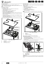
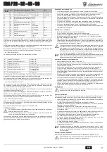
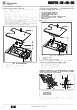
fig. 16 - Diagram of connection to external hot water tank

Key

8

Domestic hot water outlet

9

Domestic cold water inlet

10

System delivery

11

System return

2.4 Gas connection

B

Before making the connection, make sure the unit is arranged for operation with
the type of fuel available and carefully clean all the pipes of the gas system to
remove any residues that could affect proper functioning of the boiler.

The gas must be connected to the relevant connection (see fig. 22) in conformity with
current standards, with a rigid metal pipe or with a continuous surface flexible s/steel
tube, installing a gas cock between the system and boiler. Make sure all the gas connec-
tions are tight.
The gas meter must be adequate for the simultaneous use of all units connected to it.
The diameter of the gas pipe leaving the boiler does not determine the diameter of the
pipe between the unit and the meter; it must be chosen according to its length and pres-
sure losses, in conformity with current standards.

2.5 Electrical connections
Connection to the power supply

The boiler must be connected to a single-phase 230 Volt-50 Hz electric line.

B

The unit's electrical safety is only guaranteed when it is correctly connected to
an efficient earthing system in conformity with the current safety standards.
Have the efficiency and suitability of the earthing system checked by profes-
sionally qualified personnel; the Manufacturer declines any liability for damage
caused by failure to earth the system. Also make sure the electrical system is
adequate for the maximum power absorbed by the unit, as specified on the boil-
er dataplate, in particular ensuring that the section of the system's cables is
suitable for the power absorbed by the unit.

The boiler is prewired and supplied standard with connectors for connection to possible
accessory components such as circulating pumps, mixer valves, as well an electronic
thermostatic controller (see wiring diagrams). It also has a connector for connection to
the electric line. The connections to the mains must be made with a permanent connec-
tion and equipped with a double-pole switch with contact opening of at least 3 mm, inter-
posing fuses of max. 3A between the boiler and the line. Make sure to respect the
polarities (LINE: brown wire / NEUTRAL: blue wire / EARTH: yellow/green wire) when
making connections to the electric line.

Room thermostat

B

The room thermostat must have voltage-free contacts. Connecting 230 V.
to the terminals of the room thermostat will irreparably damage the flame
control electronic unit.

When connecting a room thermostat with a daily or weekly programme, or a
timer switch, do not take the power supply for these devices from their cutout
contacts. Their power supply must be taken with a direct connection from the
mains or with batteries, depending on the kind of device.

2.6 Air/fume ducts

The diameter of the connecting pipe to the flue must not be less than that of the connec-
tion on the anti-backflow device. Starting from the anti-backflow device it must have a
vertical section at least 50 cm long. The current regulations must be respected regarding
the dimensioning and installation of the flues and connection pipe.
The boiler is a 

B11BS

 type equipped with a safety device (fume thermostat) that stops

the supply of gas and shuts down the unit in case of poor draught or disturbance in the
fume exhaust. Unit shutdown is indicated on the display with the code 

F04

 (ref. cap. 3.4).

Restarting of the unit occurs automatically 20 minutes after the end of the fault that
caused the problem. In case of repeated intervention of the device, contact qualified per-
sonnel to check the flue and chimney and eliminate the fume evacuation fault.

B

This safety device must never be tampered with or deactivated. Any operation
on the device, or its replacement, must only be carried out by qualified person-
nel using the manufacturer's original replacement parts. A functional test must
be carried out after any operation on the device.

8
9

10

11

cod. 3540L893  -  Rev. 01 - 03/2018

Summary of Contents for ERA F23

Page 1: ...FOR USE INSTALLATION AND MAINTENANCE FR INSTRUCTIONS D UTILISATION D INSTALLATION ET D ENTRETIEN ES INSTRUCCIONES DE USO INSTALACI N Y MANTENIMIENTO RO INSTRUC IUNI DE UTILIZARE INSTALARE I NTRETINER...

Page 2: ...ly using the switch and or the special cut off devices In case of a fault and or poor operation deactivate the unit and do not try to repair it or directly intervene Contact pro fessionally qualified...

Page 3: ...ion 7 2 3 Plumbing connections 7 2 4 Gas connection 7 2 5 Electrical connections 7 2 6 Air fume ducts 7 3 Service and maintenance 8 3 1 Adjustments 8 3 2 Start up 9 3 3 Maintenance 9 3 4 Troubleshooti...

Page 4: ...rt mode selection button 8 Winter mode 9 DHW operation 10 Summer mode 11 Multifunction 12 C Comfort mode 13 Heating mode 14 Shutdown type fault 15 Burner On 16 All the arrows light up together on conn...

Page 5: ...10 fig 1 the boiler will only deliver domestic hot water The antifreeze system remains activated To deactivate Summer mode press the button R detail 6 fig 1 again for 1 second Heating temperature adju...

Page 6: ...fig 14 Example of compensation parallel curve offset A If the Remote Timer Control optional is connected to the boiler the above ad justments are managed according to that given in table 1 Table 1 Wat...

Page 7: ...utomatically configures the DHW function activating the display and relevant controls fig 16 Diagram of connection to external hot water tank Key 8 Domestic hot water outlet 9 Domestic cold water inle...

Page 8: ...t changed Refit the protection cap D To end TEST mode repeat the activation sequence or wait 15 minutes A After checking or adjusting the pressure make sure to seal the adjust ment screw with paint or...

Page 9: ...ty devices B If the burners do not light and the block indicator comes on after correctly car rying out the lighting procedures wait approx 15 seconds then press the button R detail 6 fig 1 The reset...

Page 10: ...d in the top part of the anti backflow device see fig 20 detail 3 To take samples 1 Remove the upper panel of the boiler 2 Remove the insulation above the anti backflow device 3 Open the fume sampling...

Page 11: ...system Vent the system F04 Fume thermostat activation after activation of the fume thermostat boiler operation is inhibited for 20 minutes Fume thermostat contact open Check the thermostat Wiring disc...

Page 12: ...Min pressure at burner G20 mbar 2 5 2 5 2 5 2 5 Max gas delivery G20 m3 h 2 68 3 69 5 24 6 52 Min gas delivery G20 m3 h 1 07 1 58 2 08 2 59 Burner nozzles G31 no x 2 x 1 75 3 x 1 75 4 x 1 75 5 x 1 75...

Page 13: ...ostat 81 Ignition electrode 82 Detection electrode 114 Water pressure switch optional 126 Fume thermostat 130 Hot water tank circulating pump optional 138 External probe 139 Remote timer control OpenT...

Page 14: ...dispositifs d isolement pr vus D sactiver l appareil en cas de panne et ou de mauvais fonctionnement en s abstenant de toute tentative de r pa ration ou d intervention directe S adresser uniquement un...

Page 15: ...ts hydrauliques 19 2 4 Raccordement gaz 19 2 5 Branchements lectriques 19 2 6 Conduits d air de fum e 19 3 Utilisation et entretien 20 3 1 R glages 20 3 2 Mise en service 21 3 3 Entretien 21 3 4 D pan...

Page 16: ...e Extinction appareil 8 Indication mode hiver 9 Indication du fonctionnement eau chaude sanitaire 10 Indication fonction t 11 Indication multifonction 12 Indication mode C Confort 13 Indication foncti...

Page 17: ...ne fournira que de l eau chaude sanitaire Le syst me antigel reste actif Pour d sactiver le mode t appuyer nouveau sur la touche R rep 6 fig 1 pendant 1 seconde R glage de la temp rature de chauffage...

Page 18: ...stance option les r gla ges ci dessus seront g r s comme indiqu dans le tableau tableau 1 Tableau 1 R glage de la pression hydraulique de l installation La pression de remplissage installation froid l...

Page 19: ...is s par ment Effectuer les raccordements lectriques comme l indique le sch ma lectrique au cap 4 Utiliser une sondeLAMBORGHINI Le syst me de contr le de la chaudi re l allumage suivant reconna t la p...

Page 20: ...d une montre pour la diminuer et dans le sens inverse pour l augmenter Rebrancher le faston s par du modureg sur la vanne gaz V rifier que la pression maximale n ait subi aucune variation Remettre en...

Page 21: ...lution des probl mes A Au cas o l alimentation lectrique vers la chaudi re vendrait manquer alors que celle ci est en fonctionnement les br leurs s teindront et se rallumeront automatiquement d s le r...

Page 22: ...ter l isolation recouvrant l antirefouleur 3 Ouvrir le point de pr l vement des fum es 4 Introduire la sonde 5 R gler la temp rature de la chaudi re sur la valeur maximum 6 Attendre 10 15 minutes pou...

Page 23: ...clenchement du thermostat s curit fum es apr s son d clenchement le fonctionne ment de la chaudi re est d sactiv pendant 20 minutes Contact de thermostat s curit fum es ouvert V rifier le thermostat C...

Page 24: ...15 0 Pression mini au br leur G20 mbar 2 5 2 5 2 5 2 5 D bit gaz puissance maxi G20 m3 h 2 68 3 69 5 24 6 52 D bit gaz puissance mini G20 m3 h 1 07 1 58 2 08 2 59 Gicleurs br leur G31 nbre x 2 x 1 75...

Page 25: ...Thermostat d ambiance 81 lectrode d allumage 82 lectrode de d tection 114 Pressostat eau en option 126 Thermostat fum es 130 Circulateur ballon option 138 Sonde ext rieure 139 Chronocommande distance...

Page 26: ...n u otro dispositivo de corte En caso de aver a o funcionamiento incorrecto del equipo desconectarlo y hacerlo reparar nicamente por un t cnico autorizado Acudir exclusivamente a personal autorizado...

Page 27: ...exiones hidr ulicas 31 2 4 Conexi n del gas 31 2 5 Conexiones el ctricas 31 2 6 Conductos de aire y humos 31 3 Servicio y mantenimiento 32 3 1 Regulaciones 32 3 2 Puesta en servicio 33 3 3 Mantenimien...

Page 28: ...do del aparato 8 Indicaci n de modalidad Invierno 9 Indicaci n de funcionamiento en producci n de ACS 10 Indicaci n de modalidad Verano 11 Indicaci n multifunci n 12 Indicaci n de modalidad C Confort...

Page 29: ...inistra agua sanitaria El sistema antihielo permanece operativo Para desactivar la modalidad Verano pulsar nuevamente la tecla R 6 fig 1 durante un segundo Regulaci n de la temperatura de calefacci n...

Page 30: ...rmente se gestionan seg n lo indicado en la tabla 1 Tabla 1 Regulaci n de la presi n hidr ulica de la instalaci n La presi n de carga con la instalaci n fr a le da en el hidr metro de la caldera tiene...

Page 31: ...encender la caldera el sis tema de control reconoce la sonda del acumulador y se configura autom ticamente ac tivando la pantalla y los controles de la funci n para agua sanitaria fig 16 Esquema para...

Page 32: ...Para salir del modo TEST repetir la secuencia de activaci n o dejar pasar quince minutos A Tras controlar la presi n o regularla es obligatorio sellar el tornillo de re gulaci n con pintura o con un...

Page 33: ...iclo de encendido Si despu s del segundo intento los quemadores siguen sin encenderse consultar el p rrafo Soluci n de proble mas A Si se interrumpe el suministro el ctrico mientras la caldera est en...

Page 34: ...aldera 2 Quitar el aislante que cubre el cortatiro 3 Abrir el punto de toma de humos 4 Introducir la sonda 5 Regular la temperatura de la caldera al m ximo 6 Esperar a que transcurran unos diez o quin...

Page 35: ...del termostato de humos tras la interven ci n del termostato de humos el funcionamiento de la caldera se inhabilita durante 20 minutos Contacto del termostato de humos abierto Controlar el termostato...

Page 36: ...20 mbar 15 13 15 15 Presi n m nima quemador con G20 mbar 2 5 2 5 2 5 2 5 Caudal m ximo G20 m3 h 2 68 3 69 5 24 6 52 Caudal m nimo G20 m3 h 1 07 1 58 2 08 2 59 Inyectores quemador G31 n x 2 x 1 75 3 x...

Page 37: ...72 Termostato de ambiente 81 Electrodo de encendido 82 Electrodo de detecci n 114 Presostato del agua opcional 126 Termostato de los humos 130 Bomba de circulaci n del acumulador opcional 138 Sonda e...

Page 38: ...ntrerup torului instala iei i sau cu ajutorul dispozitivelor corespunz toare de blocare n caz de defec iune i sau de func ionare defectuoas a aparatului dezactiva i l evit nd orice ncercare de repara...

Page 39: ...rdurile hidraulice 43 2 4 Racordarea la gaz 43 2 5 Racordurile electrice 43 2 6 Conducte aer gaze arse 43 3 Exploatarea i ntre inerea 44 3 1 Regl rile 44 3 2 Punerea n func iune 45 3 3 ntre inerea 45...

Page 40: ...t selectare mod Economy Comfort Aprindere Stingere aparat 8 Indicator mod Iarn 9 Indicator func ionare ap cald menajer 10 Indicator mod Var 11 Indicator multifunc ional 12 Indicator modul C Comfort 13...

Page 41: ...ai ap cal d menajer R m ne activ sistemul anti nghe Pentru a dezactiva modul Var ap sa i din nou pe tasta R det 6 fig 1 timp de 1 se cund Reglarea temperaturii n circuitul de nc lzire Cu ajutorul buto...

Page 42: ...central este conectat Croncomanda la distan op ional regl rile de mai sus trebuie efectuate conform indica iilor din tabel 1 Tabel 1 Reglarea presiunii hidraulice din instala ie Presiunea de umplere...

Page 43: ...se configureaz automat activ nd afi ajul i comenzile relative la func ia de prepararea a apei calde menajere fig 16 Schema de conectare la un boiler extern Legend 8 Ie ire ap menajer 9 Intrare ap rece...

Page 44: ...a de gaz Verifica i ca presiunea maxim s nu fie schimbat Pune i la loc capacul de protec ie D Pentru a ie i din modul TEST repeta i secven a de activare sau a tepta i 15 minute A Dup ce s a efectuat c...

Page 45: ...dere arz toarele nu se aprind iar indicatorul de blocare se lumineaz a tepta i aproximativ 15 secun de i apoi ap sa i butonul R det 6 fig 1 Unitatea reini ializat va repeta ci clul de aprindere Dac ni...

Page 46: ...un punct pentru prelevarea gazelor arse vezi fig 20 det 3 Pentru a efectua prelevarea proceda i astfel 1 Scoate i panoul superior al centralei 2 Scoate i izolatorul aflat deasupra dispozitivul antire...

Page 47: ...ala ie F04 Interven ia termostatului pentru gaze arse dup interven ia termostatului gaze arse func ionarea centralei e blocat timp de 20 minute Contact termostat gaze arse deschis Verifica i termostat...

Page 48: ...0 13 0 15 0 15 0 Presiune min la arz tor G20 mbar 2 5 2 5 2 5 2 5 Debit gaz max G20 m3 h 2 68 3 69 5 24 6 52 Debit gaz min G20 m3 h 1 07 1 58 2 08 2 59 Duze arz tor G31 nr x 2 x 1 75 3 x 1 75 4 x 1 7...

Page 49: ...72 Termostatul de camer 81 Electrod de aprindere 82 Electrod de detectare 114 Presostat ap op ional 126 Termostat gaze arse 130 Pomp de circula ie boiler op ional 138 Sond extern 139 Cronocomand la di...

Page 50: ...50 ERA F 23 32 45 56 RU B B A Lamborghini Calor S p A 24 24 10 cod 3540L893 Rev 01 03 2018...

Page 51: ...ERA F 23 32 45 56 51 RU 1 52 1 1 52 1 2 52 1 3 52 1 4 53 2 55 2 1 55 2 2 55 2 3 55 2 4 55 2 5 55 2 6 55 3 56 3 1 56 3 2 57 3 3 57 3 4 59 4 59 4 1 59 4 2 60 4 3 60 4 4 61 cod 3540L893 Rev 01 03 2018...

Page 52: ...LAM BORGHINI ERA F 23 32 45 56 A sez 2 3 1 2 1 1 2 3 4 5 6 7 Economy Comfort 8 9 10 11 12 C 13 14 15 16 13 1 2 9 1 3 conomy ComforT 12 1 N 7 1 1 2 1 ECO CON N 7 1 1 3 4 B sez 2 3 9 13 11 15 16 2 5 1...

Page 53: ...10 1 R 6 1 1 3 4 1 30 C 85 C 45 C 9 10 C 65 C 1 2 1 10 I I I I I I I I IIII I I I I I I I I I I IIII I I I I I I I I I I IIII I I I I I I I I I I IIII I I I I IIII I I I I I I I I I I I I IIII I I I I...

Page 54: ...I I I I I I I I I I I IIII I I I I I I I I I I I I I I I I I I I I I I I I I I I I I I I I I I I IIII I I I I I I I I I I IIII I I I I I I I I I I IIII I I ECO COMFORT Economy N 7 1 COMFORT N 7 1 20 3...

Page 55: ...45 56 55 RU 2 2 1 B 2 2 A 2 3 20 C B 22 B 25 Fr 1 F 10 CaCO3 15 F 236 88 16 cap 4 LAMBORGHINI 16 8 9 10 11 2 4 B 22 2 5 230 50 B 3 3 A B 230 2 6 0 5 B11BS F04 cap 3 4 20 B 8 9 10 11 cod 3540L893 Rev...

Page 56: ...ervice 10 2 P01 1 10 Service Reset 10 tS In Hi rE tS In Hi History rE Reset History Reset tS 24 Service I I I I I I I I IIII I I I I I I I I I I IIII I I I I I I I I I I IIII I I I I I I I I I I IIII...

Page 57: ...R 6 1 A sez 1 3 sez 4 3 3 3 B 1 A 12 P12 31 85 C 85 C 13 P13 0 255 30 14 P14 0 255 120 15 P15 0 100 100 16 P16 55 65 C 17 P17 0 20 C 18 P18 70 85 C 19 P19 Non modificabile 0 20 P20 Non modificabile 4...

Page 58: ...ERA F 23 32 45 56 58 RU 19 B 19 1 2 3 4 20 3 1 2 3 4 5 6 10 15 7 A 20 1 2 3 A C D 21 21 1 2 3 1 2 3 4 1 2 3 4 0 5 1 2 3 A C D D cod 3540L893 Rev 01 03 2018...

Page 59: ...A03 F04 20 A06 F10 1 F11 F14 2 F34 170 F35 F37 F39 A41 F42 F50 odureg A B C D E F G A1 A2 A3 ERA F 23 450 137 134 65 480 130 70 1 1 2 1 1 2 1 2 ERA F 32 450 94 91 22 530 150 80 ERA F 45 600 126 123 8...

Page 60: ...0 15 0 13 0 15 0 15 0 G20 2 5 2 5 2 5 2 5 G20 3 2 68 3 69 5 24 6 52 G20 3 1 07 1 58 2 08 2 59 G31 x 2 x 1 75 3 x 1 75 4 x 1 75 5 x 1 75 G31 37 0 37 0 37 0 37 0 G31 35 0 31 0 35 0 35 0 G31 6 0 6 0 6 0...

Page 61: ...38 139 OpenTherm 278 7 6 5 4 3 2 1 11 10 9 8 7 6 5 4 3 2 1 T1 T2 X7 7 6 5 4 3 2 1 6 5 4 3 2 1 X5 F1 F2 X1 X2 X4 X3 X6 X8 X10 2 1 T T 278 L N 230V 50Hz 138 L N 4 5 6 7 8 9 10 11 12 13 14 15 16 17 18 12...

Page 62: ...ECTIVES IN FORCE THE DECLARATION OF CONFORMITY MAY BE REQUESTED FROM THE MANUFACTURER 58 FR LE MARQUAGE ATTESTE QUE LES PRODUITS SONT CONFORMES AUX EXIGENCES ESSENTIELLES DE L ENSEMBLE DES DIRECTIVES...

Page 63: ......

Page 64: ...55 300 117393 7 495 785 55 00 7 499 500 00 01 0DGH LQ WDO DEULTXp HQ WDOLH Fabricado en Italia Fabricat n Italia VIA n 047 6...

Reviews: