Vega Customer Applications Manual
Section 10 - Combining Modules
Rev. A3: October 2003
Page 36 of 48
Remote Sense
Remote sense can be used to compensate for the drop in voltage
along the load cables or for the drop in
voltage across blocking diodes. It moves the point at which the voltage
is sensed from the outputs of the power supply to some other point in
the system, normally the load, or a backplane.
Always observe the following general rules for remote sense operation:
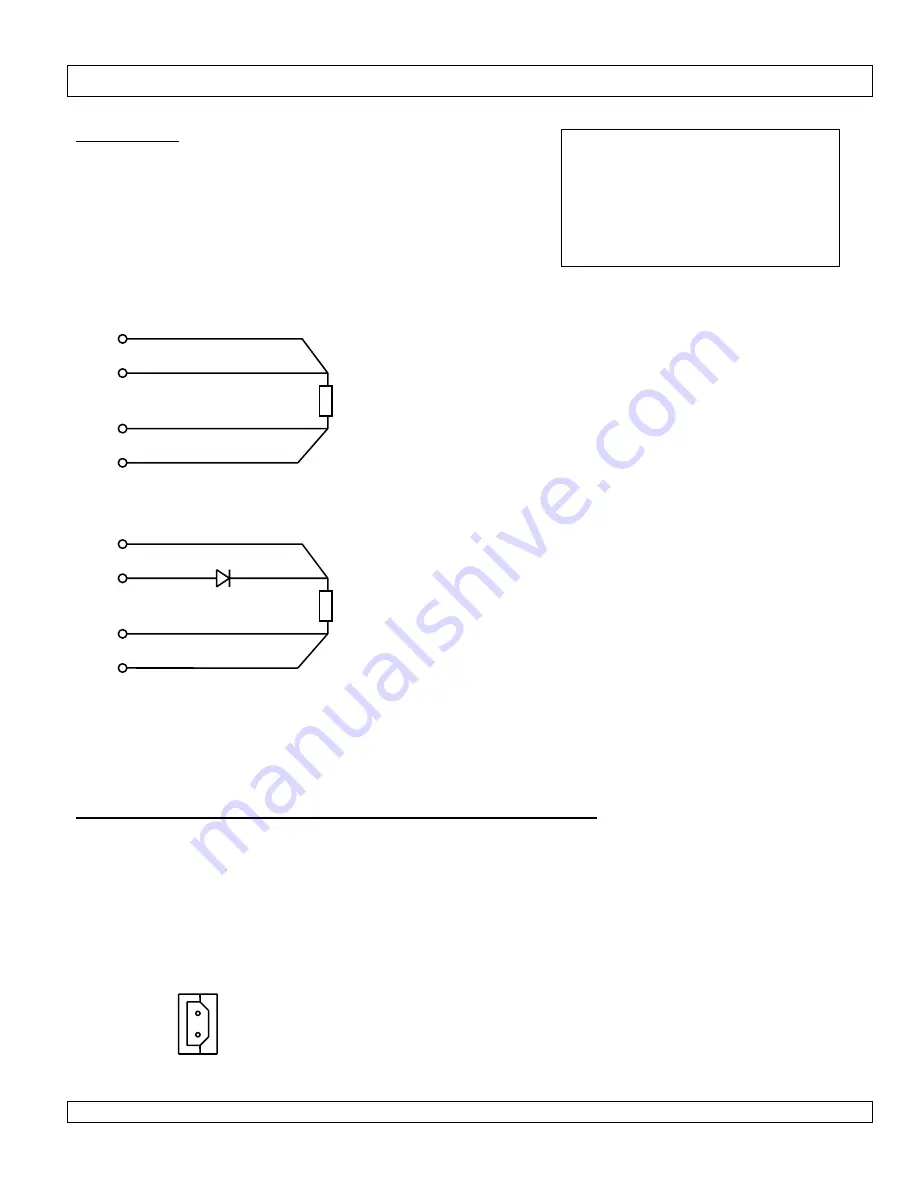
Remote Sense connection and 1slot, 1.5slot, 2slot Combination Modules.
1slot, 1.5slot and 2slot modules have remote sense fitted as standard. When 2 modules of this type are combined,
remote sense can still be used.
One of the combined modules has the +V power terminal. The same module has a 2pin molex with +S and -S pins.
Connect the +S from the molex on this module to the +ve side of the load.
+ SENSE
- SENSE
Ensure that the remote sense cables are TWISTED PAIRS.
PCB tracks for remote sense should be run back to back.
Ensure that the remote sense cables / tracks are as short as
possible.
Ensure that the sense cables are not twisted together with the
power cables.
PCB power tracks and remote sense tracks should be kept
away from each other as far as is possible.
Do NOT fit components (resistor, inductor or diode) into remote
sense lines. This will make the system unstable.
See the data sheets for each module to see the MAXIMUM
voltage drop that remote sense can compensate for. Do not
exceed this value (typically 0.75V, but varies for each module)
Load
Load
+V
+V
-V
-V
-S
-S
+S
+S
Mating connector information:
Note: housing and pins supplied with
each power supply.
Housing: Molex 50-37-5023
Crimp pin: Molex 08-70-1039
Hand Crimp Tool: 11-26-0167
(Japan)
Or 11-01-0194(Europe or USA)


