laguna Smart Shop M2 Owner'S Manual Download Page 49

Smart Shop "M" Maker 2

49

Run procedure to calculate Tool Offsets (Cont’d.)
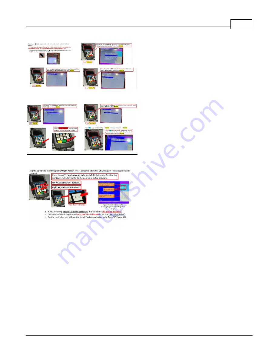
Set XY Work Origin. 

Start with Tool 1, Tool 1 = Master Tool Bit.
Press and hold the “

MENU

” button --> press “

TOOLSET

” button -->release both buttons. 

Once Tool 1 has touched off, Switch to Tool 2, using the Tool Switch button.  

Press and hold the “

MENU

” button --> press “

TOOLSET

” button --> release both buttons.

Proceed to Touch Off all Tools in ascending order. 

Switch back to Tool 1, using the Tool Switch button. Offsets are now calculated.

Summary of Contents for Smart Shop M2

Page 1: ...ecember 2021 Smart Shop Smart Shop M Maker 2 3 Phase Power Copyright Laguna Tools 2021 User Guide for the Smartshop Machines equipped with the RichAuto B57E HHC Handheld Controller Basic Operations Qu...

Page 2: ......

Page 3: ...lina 825 Bistline Dr Ste 101 West Columbia SC 29172 U S A Phone 1 800 234 1976 Minnesota 5250 West 74th St Edina MN 55439 U S A Phone 1 949 474 1200 lagunatools com supermaxtools com lagunacleanair co...

Page 4: ...her and the author make no claim to these trademarks While every precaution has been taken in the preparation of this document the publisher and the author assume no responsibility for errors or omiss...

Page 5: ...29 Tool Changing 30 Multiple Tool Program 31 Multiple Tool Program Cont d 34 Transfer G Code Program 35 Loading Program to Cut Load Program 37 Setting XY Work Origin 38 Setting Z Work Origin 42 Under...

Page 6: ...1 Installation Outline 62 Default Machine Settings Protocols 63 Schematics 64 Creating a G Code File using V Carve Programming 66 Appendix 68 Exploded Normal View 69 Dealer Warranty 70 CNC Limited War...

Page 7: ...you to read and understand this manual The information it contains is provided for your safety while assembling and operating this machine Safety Signs and Call Outs An imminently hazardous situation...

Page 8: ...O FOLLOW THESE RULES MAY RESULT IN SERIOUS PERSONAL INJURY FOR YOUR OWN SAFETY READ AND UNDERSTAND THE INSTRUCTION MANUAL BEFORE OPERATING THE MACHINE Learn the unit s application and limitations as w...

Page 9: ...Smart Shop M Maker 2 9 exposure level limits will vary from country to country...

Page 10: ...ement of the electric cord or plug is necessary do not connect the equipment grounding conductor to a live terminal Check with a qualified electrician or service personnel if the grounding instruction...

Page 11: ...Fig C The tool has a grounding plug that looks like the plug illustrated in Fig C Make sure the tool is connected to an outlet having the same configuration as the plug No adapter is available or shou...

Page 12: ...application other than that for which it was designed If you have any questions relative to a particular application DO NOT use the machine until you have first contacted the manufacturer to determin...

Page 13: ...R REMOVE SWITCH KEYS OR LOCK OUT MACHINE TO PREVENT UNAUTHORIZED USE ESPECIALLY AROUND CHILDREN MAKE YOUR WORKSHOP KID PROOF DANGEROUS ENVIRONMENTS DO NOT USE MACHINERY IN AREAS THAT ARE WET CLUTTERED...

Page 14: ...BECOME DANGEROUS PROJECTILES UPON STARTUP NEVER LEAVE CHUCK KEYS WRENCHES OR ANY OTHER TOOLS ON MACHINE ALWAYS VERIFY REMOVAL BEFORE STARTING USE CORRECT TOOL FOR THE JOB ONLY USE THIS TOOL FOR ITS I...

Page 15: ...ING AWAY NEVER LEAVE MACHINE RUNNING WHILE UNATTENDED MAINTAIN WITH CARE FOLLOW ALL MAINTENANCE INSTRUCTIONS AND LUBRICATION SCHEDULES TO KEEP MACHINE IN GOOD WORKING CONDITION A MACHINE THAT IS IMPRO...

Page 16: ...Smart Shop M Maker 2 3 Phase Power 16 Product Specifications...

Page 17: ...Smart Shop M Maker 2 17 Machine Overview...

Page 18: ...tive with any Delivery Restrictions Customer is required to have a forklift 6000lb or larger is recommended with 72 forks or fork extensions and operator Note any visible damage torn packaging scuffs...

Page 19: ...of maintenance cleaning or misuse abuse the customer will be responsible for the cost to replace the item part plus all related shipping charges We require that the defective item part be returned to...

Page 20: ...there are no damages to either the machine or the parts you ve received See the inventory page to cross reference the parts you should receive with your M This machine is heavy If you have any doubt a...

Page 21: ...front of the machine to allow you to work on it comfortably 2 There should be sufficient area at the back of the machine to allow access for adjustments and maintenance to be conducted 3 Adequate ligh...

Page 22: ...equipment which may be placed on the band saw Also consider the weight of the operator and any materials which may be stored around the machine when selecting a location for your machine This machine...

Page 23: ...Smart Shop M Maker 2 23 Operation Instructions...

Page 24: ...were placed in your order 3 Make sure that Area where the machine will be placed has appropriate electrical voltage and amperage per machine s Electricians and service staff are welcome to contact our...

Page 25: ...hine needs to be homed each time the machine is powered when positioning is lost This resets your machine coordinates origin relative to the home switches and flags The tool locations are relative to...

Page 26: ...Power 26 Basic Button Functions The B57E HHC Rich Auto Motion Control System uses 1 button and 2 button combination functions Only the most used button functions are covered in this section and the se...

Page 27: ...what method works best for your application before proceeding c Always consider clearance between the router bit and table clamps When the machine changes tools it will need to travel to the back of...

Page 28: ...rocedure Tool Changing Must have 90 95 PSI Air Pressure in System before continuing 1 A tool can be inserted or removed in Two Ways a Manually Using the Red Manual Tool Release Button on the side of t...

Page 29: ...Air Pressure in System before continuing Verify that the machine is connected to an Air Supply 2a The tool changer needs 6 bar 6 5 bar or 87 psi 95 psi 2b Use the pressure regulators See Figures Belo...

Page 30: ...listed from Left to Right Machine will then switch from current Tool in Spindle to Tool Selected Press REF OK Button Note Ensure current tool clip is Empty otherwise spindle will crash into a tool co...

Page 31: ...to an air supply 1 Power on Machine Turn the rotary switch to the ON position Turn the key to the ON position Press the Control Power ON OFF button located on the control panel 2 Home Machine Verify...

Page 32: ...regularly Ensure that the slots in the collets are free of debris 2 Press the collet into the spindle nut until it snaps into place 3 Thread on the nut and collet by hand onto the tool cone 4 Insert t...

Page 33: ...Smart Shop M Maker 2 33...

Page 34: ...one does intend to use a Use the manual tool release button located on the tool head to load the tool cone into the spindle b It is pertinent that the spindle releases and engages the tool cone repea...

Page 35: ...Smart Shop M Maker 2 35 Transfer G Code Program Transferring onto a USB and into the Controller s Internal Memory...

Page 36: ...Smart Shop M Maker 2 3 Phase Power 36...

Page 37: ...Smart Shop M Maker 2 37 Loading Program to Cut Load Program...

Page 38: ...cted Setting XY Work Origin SECTION Cont d Verify Coordinate System See Photo Illustration Below Figure 1 Control Screen after Loading Program and Setting Work Origin b If not in work piece hold Menu...

Page 39: ...which tool cone is currently in the spindle and compare to the CurSpindl parameter on the controller run screen If Current Tool Number is Not Tool 1 then switch tools using Tool Switch Function See B...

Page 40: ...rogram s Origin Point This is determined by the CNC Program that was previously created a If you are using Vectric s V Carve Aspire Software it is called the XY Datum Position b Once the spindle is in...

Page 41: ...Press the up Y and down Y right X left X Buttons to Scroll or Jog up down right left to the to the desired selected program Note One must be in Work Piece Mode Remember Origin Office One starts work...

Page 42: ...og Speed to Low and carefully move the spindle down until the desired Z Zero Position is obtained Z Zero position is determined by the software either top of the material or bottom of the material Ver...

Page 43: ...1mm of your material iii Must set by using Tool 1 b Press the ZC 0 button c On the controller you will see the Z axis coordinate go to zero Figure 1 d Optional Press REF OK Button x2 Twice Pressing RE...

Page 44: ...the E STOP Button on the control cabinet In most cases the Stop Cancel Button on the Handheld Controller HHC is a preferred stopping method h Press the RUN PAUSE DELETE Button to start the program i...

Page 45: ...tons i Y will increase the feed rate by 10 ii Y will decrease the speed by 10 iii The max speed is determined by the program file l Program End At the end of a program the spindle will STOP and the Z...

Page 46: ...s not the origin Tool positions and TTO switch location are set relative to machine coordinates Press MENU ZRN 0 to switch to Workpiece 0 Hold down the MENU 1 9 Buttons to move between different origi...

Page 47: ...Smart Shop M Maker 2 47 Transitioning between workpieces will in turn transition between X Y and Z offsets made in each Workpiece...

Page 48: ...ng Tools and Touching Off Prepare the Machine Prepare all tool cones for the job and place into tools corresponding holders Prepare all Tool Cones for the job and place into Tools corresponding holder...

Page 49: ...d hold the MENU button press TOOLSET button release both buttons Once Tool 1 has touched off Switch to Tool 2 using the Tool Switch button Press and hold the MENU button press TOOLSET button release b...

Page 50: ...Smart Shop M Maker 2 3 Phase Power 50 Note Cannot touch off plaining bits...

Page 51: ...Smart Shop M Maker 2 51 Multiple Tool Program Touch Off Tool 1 and any subsequent Tools after that switch back to Tool 1 for manual Touch Off Set Z work origin with Tool 1 Run Program...

Page 52: ...Spindle 1 and tool 1 is in the spindle Manually jog the spindle into a safe location by the tool rack The machine will return to the starting position after changing tools Press and hold the MENU but...

Page 53: ...Smart Shop M Maker 2 53 Setting the Origin XY Datum Set XY Work Origin...

Page 54: ...Smart Shop M Maker 2 3 Phase Power 54 Set Z Work Origin Set Z work origin with Tool 1...

Page 55: ...Smart Shop M Maker 2 55 Run Program Run Program...

Page 56: ...are set relative to machine coordinates Press MENU ZRN 0 to switch to Workpiece 0 Hold down the MENU 1 9 Buttons to move between different origin points This Machine can have up to 9 Origin Points on...

Page 57: ...Smart Shop M Maker 2 57...

Page 58: ...ebris Note Do to leave Spindle in the Tool for a prolonged period of time Spindle could Rust into the tool over time Make sure to remove Spindle from Tool after being used Schedule Document into ones...

Page 59: ...tool cone into the spindle using the manual tool release button Using the handheld controller s jog control carefully guide the cone into the tool rack Remove Dust Hood to visually see Tool Cone Recom...

Page 60: ...60 Scroll down to ATC setup REF OK Scroll up to ATC position REF OK Select Tool desired Press Cancel Select desired Axis Press Run Pause Delete Input Valves Next desired Axis until all X Y Z Z always...

Page 61: ...eter needs to be adjusted follow this path MENU Menu function user interface machine setup Toolset setup C A D position select with REF OK button Select InPosition by pressing RUN PAUSE DELETE to chan...

Page 62: ...Smart Shop M Maker 2 3 Phase Power 62 Installation Outline...

Page 63: ...Smart Shop M Maker 2 63 Default Machine Settings Protocols...

Page 64: ...Smart Shop M Maker 2 3 Phase Power 64 Schematics...

Page 65: ...Smart Shop M Maker 2 65...

Page 66: ...Smart Shop M Maker 2 3 Phase Power 66 Creating a G Code File using V Carve Programming...

Page 67: ...Smart Shop M Maker 2 67...

Page 68: ...Smart Shop M Maker 2 3 Phase Power 68 Appendix HITECO SPINDLE PNEUMATIC SPECIFICATIONS...

Page 69: ...Smart Shop M Maker 2 69 Exploded Normal View...

Page 70: ...y accident neglect lack of or inadequate dust collection misuse abuse or damage caused where repair or alterations have been made or attempted by others NOTE Issuing an RMA number is for referencing m...

Page 71: ...Smart Shop M Maker 2 71...

Page 72: ...r modifications determined on a case by case basis Software purchased through Laguna Tools Inc is not covered under this warranty and all technical support must be managed through the software provide...

Page 73: ...three issues 1 The machine cannot move a specified amount Either the origin needs to be moved or it is out of place 2 There is an operator error using the software design 3 Tools need to be touched of...

Page 74: ...e Way Suite 200 Grand Prairie Texas 75050 U S A Phone 1 800 234 1976 Huntington Beach 7291 Heil Ave Huntington Beach CA 92647 U S A Phone 1 949 474 1200 South Carolina 825 Bistline Dr Ste 101 West Col...

Page 75: ...rand Prairie Texas 75050 U S A Phone 1 800 332 4094 Huntington Beach 7291 Heil Ave Huntington Beach CA 92647 U S A Phone 1 949 474 1200 South Carolina 825 Bistline Dr Ste 101 West Columbia SC 29172 U...

Reviews: