3. ASSEMBLY & SETUP
12
5.
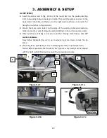
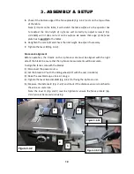
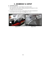
Check if the bottom edge of the fence plate
E
(Fig. 3-4.2) rests on the top surface
of the table.
Note: If it rests on the table, it will scratch the table surface. So, the operator has
to readjust the ride height of rip fence unit correctly by adjust screws
F
(Fig.
3-4.2a&b) until it does not rest on the surface. Be aware that edge of the fence
plate has to
parallel
to the tables.
6.
Retighten the cam bolt and check the ride height. Re-adjust if necessary.
7.
Tighten the lever
D
(Fig. 3-4.2).
Fence scale alignment
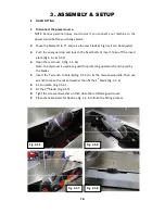
Before operation, the 0 mark on the rip fence scale must be aligned with the right
side of the blade to ensure that the rip fence measurements will be accurate.
To align the fence scale with the blades:
(1) Disconnect the power source
(2) Set the blade to 0° with the tilting wheel (90° with the cast iron table)
(3) Raise the saw blade up as far as it can go.
(4) Tighten the lever
A
and knob
B
(Fig. 3-4.2) for fixing the rip fence unit.
(5) Measure the distance
C
(Fig. 3-4.2)
and check if the distance value is matched to
the value on scale rule.
Note: the lever D
(Fig. 3-4.2) must be tighten to ensure the fence plate
E
(Fig.
3-4.2) cannot be moved or shaking.
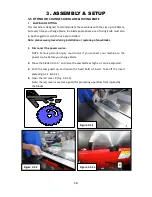
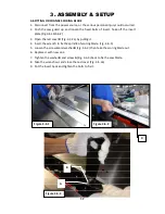
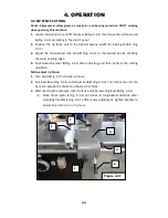
Figure 3-4.2
A
C
D
E
B
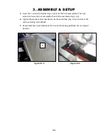
Figure 3-4.2a
Figure 3-4.2b
F
Summary of Contents for MTST5S-0135
Page 3: ......
Page 36: ......
Page 37: ...MTST5S 0135 ASSEM1 1 5 1...
Page 39: ...MTST5S 0135 ASSEM1 3 3 3...
Page 42: ...MTS5S 0135 ASSEM3 1 1 6...
Page 44: ...MTST5S 0135 ASSEM3 3 8...
Page 46: ...MTST5S 0135 ASSEM3 4 2 10...
Page 48: ...MTST5S 0135 ASSEM 4 1 12...
Page 50: ...MTST5S 0135 ASSEM5 2 14...
Page 52: ...MTST5S 0135 ASSEM6 2 16...
Page 54: ...MTST5S 0135 ASSEM6 4 18...
Page 56: ...MTST5S 0135 ASSEM10 1 20...


