


SINGLE 01.06.2019
English / Englisch
TRANSPORT AND STORAGE
6
6.1.1 TRANSPORT ON FLAT SURFACES OR OVER SMALL
LANDINGS
1
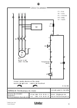
Switch off the machine and pull the power plug out of the
socket!
2
Pull the adjusting lever on the handle towards you to release
the lock of the guide tube (fig. .35, 1). Push the guide tube into
and past the vertical position until it reaches the mechanical
stop (fig. .35, 2).
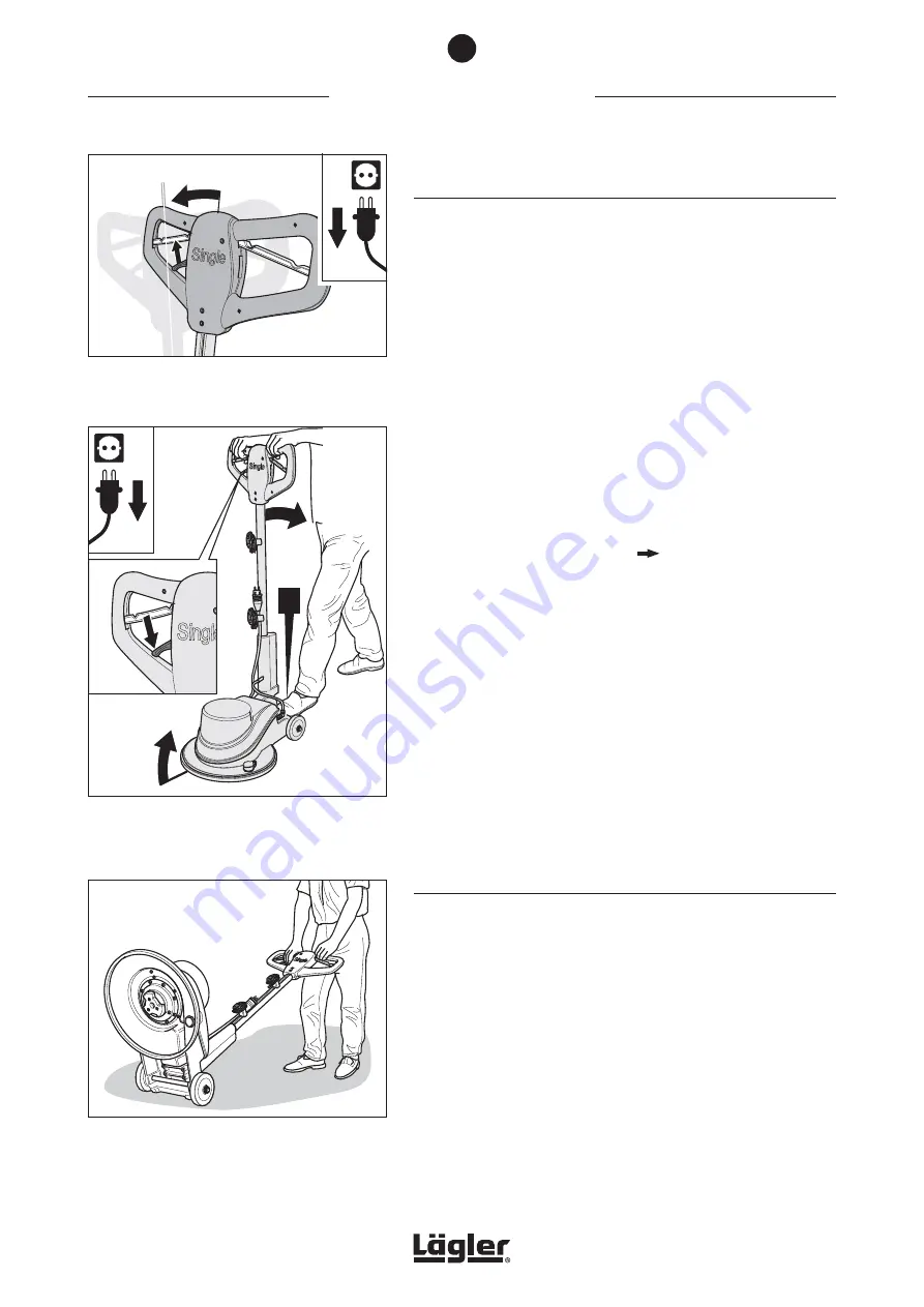
3
Release the adjusting lever so that the guide tube can engage
again (fig. 36, 1). Carefully tilt the machine backwards on the
wheels. As you do so, steady the machine with your foot to
stop it rolling away (fig. 36, 2).
Please ensure that the machine is stable before commencing
work!
4
Remove the sanding plate (
Section 5.2, Changing the
sanding plate
).
5
Lift the handle upwards with both hands until you are comfort-
ably standing (fig. 37).
6
Now you can push or pull the machine (fig. 37).
In this position the machine can be held and moved with little
effort.
7
Pull the machine slowly and carefully over small landings
such as doorsills so that the machine cannot slip out of your
hand!
6.1.2 TRANSPORT OVER LARGER LANDINGS, STAIRS OR THE
LIKE
In order to transport the machine out of the vehicle, over stairs or
other large landings, the machine must be carried.
In order to facilitate this, the machine can be dismantled into three
parts: the guide tube as one element, the sanding plate and the
drive unit (machine housing with motor).
1
Switch off the machine and pull the power plug out of the
socket!
2
Take the motor cable and the extension cable out of the cable
holder on the guide tube.
Fig. 36
Release the adjusting lever (1) and carefully tilt
the machine backwards. Steady the machine with
your foot to stop it rolling away (2) and
ensure that
the machine is stable
!
Fig. 37
Only move the machine in this position over flat
surfaces or small landings.
Single
22
11
!
22
11
Fig. 35
Pull the adjusting lever to release the lock (1)
and push the guide tube up until it reaches the
mechanical stop (2).
32


