LaCie 12big Rack Network
System Overview
User Manual
page 15
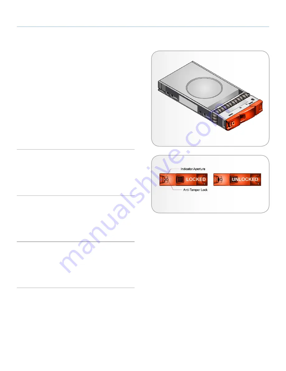
1.9. Drive Carrier Module
The Drive Carrier module comprises a hard disk mounted in a car-
rier. Each drive bay will house a single Low Profile 1.0 inch high, 3.5
inch form factor disk drive in its carrier. The carrier has mounting
locations for SAS/SATA drives.
Each disk drive is enclosed in a sheet steel carrier which provides
excellent thermal conduction, radio frequency and electro-magnetic
induction protection and affords the drive maximum physical protec-
tion.
The front cap also supports an ergonomic handle which provides the
following functions:
✦
Camming of carrier into and out of drive bays.
✦
Positive ‘spring loading’ of the drive/backplane connector.
1.9.1. Drive Status Indicator
Disk drive status is monitored by a Green LED and an Amber LED
mounted on the front of each Drive Carrier module, under ESI pro-
cessor control, shown in
Fig. 10
. Please refer to
4.2.4. Drive Carrier
Module LEDs
for a description of the LED states.
1.9.2. Anti-tamper Locks
Anti-tamper locks are fitted in the drive carrier handles (
Fig. 10
)
and are accessed through the small cutout in the latch section of
the handle. These are provided to disable the normal ‘pinch’ latch
action of the carrier handle.
1.9.3. Dummy Drive Carrier Modules
Dummy Drive Carrier modules are provided for fitting in all unused
drive bays. They are designed as integral drive module front caps
with handles and must be fitted to all unused drive bays to maintain
a balanced airflow.
Fig. 09 - Drive Carrier Module
Fig. 10 - Anti-tamper locks


