


Hydraulic System Maintenance
83
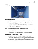
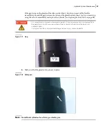
Figure 7
-
13 Optional Maximizer
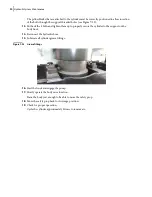
Inspecting the Pump
If the pump is adequately maintained and works smoothly, it will provide a satisfactory output.
However, if the pump whines, vibrates or rattles, apply the following inspection procedure.
To inspect the pump, proceed as follows:
1.
Ensure that the parking brake is applied and that the vehicle is tagged out for maintenance
purposes.
2.
Start the engine and engage the hydraulic pump.
N
OTE
:
The pump should turn freely without any excessive noise or vibrations.
3.
Inspect the connections for any loose fittings.
4.
Check underneath the pump for any oil leaks.
5.
If there is no electrical power, refer to the electrical schematics provided with the truck.
Adjusting Main Relief Valve Pressure
It is recommended to verify the pressure setting once every month to prevent damage to the
equipment and make sure it operates as efficiently as possible. If the pressure is not at the
recommended setting, the main relief valve needs to be readjusted. Refer to the pressure adjustment
table (see
on page 85) for proper settings.
Most of the hydraulic valve sections operate at 2000 psi except for the Maximizer section, if equipped.
For details, refer to the hydraulic system schematics.
Summary of Contents for Top Select
Page 1: ...TOP SELECT TM MAINTENANCE MANUAL...
Page 2: ......
Page 3: ...TOP SELECT MAINTENANCE MANUAL...
Page 8: ...vi Table of Contents...
Page 34: ...26 Safety...
Page 40: ...32 General Cleanliness...
Page 72: ...64 Loading Container Maintenance...
Page 104: ...96 Preventive Maintenance...
Page 121: ...Lubrication 113 Figure 11 2 Body hinges Grease Fittings on Body Figure 11 3 Tailgate and hooks...
Page 122: ...114 Lubrication Figure 11 4 Partition Figure 11 5 Optional Maximizer Location of lube zerks...
Page 123: ...Lubrication 115 Figure 11 6 Roof hinges and loading cylinders...
Page 124: ...116 Lubrication Figure 11 7 Lube chart...
Page 132: ...124 Troubleshooting...
Page 134: ...126 Hydraulic and Pneumatic Circuit Diagrams Hydraulic Schematics Single Side Bucket...
Page 135: ...Hydraulic and Pneumatic Circuit Diagrams 127 Single Side Bucket w Maximizer...
Page 136: ...128 Hydraulic and Pneumatic Circuit Diagrams Dual Side Bucket...
Page 137: ...Hydraulic and Pneumatic Circuit Diagrams 129 Dual Side Bucket w Maximizer...
Page 139: ...Hydraulic and Pneumatic Circuit Diagrams 131 Air System Schematics TS 1000 w Options...
Page 140: ...132 Hydraulic and Pneumatic Circuit Diagrams TS 2000 w Options...