


74
Hydraulic System Maintenance
Lubricate and inspect all cylinder mounting points (pins, retaining bolts, etc.).
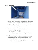
To perform an external inspection, do the following:
1.
Verify that all hose and pipe connections are tight and that there are no external leaks.
2.
Inspect all cylinder heads for any leaks.
3.
Inspect the surface of all the cylinder rods for unusual wear or scratches.
4.
On the hoist cylinder, inspect the air bleeder for any leaks. Tighten if necessary.
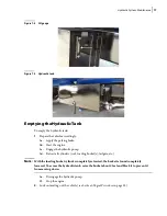
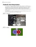
Main Hydraulic Valve
Located underneath the body floor rear section, the main hydraulic valve that is used on the T
OP
S
ELECT
™ integrates all hydraulic functions into one assembly. This valve is air-actuated with in-cab
and outside control levers.
The number of work sections composing this valve goes from 3 to 5, depending on the truck’s
configuration and the optional equipment chosen.
Figure 7
-
1 Main valve (3 sections)
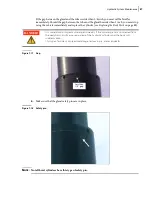
Check the shut-off valve on the suction line is completely open before engaging the
hydraulic system.
WARNING!
Summary of Contents for Top Select
Page 1: ...TOP SELECT TM MAINTENANCE MANUAL...
Page 2: ......
Page 3: ...TOP SELECT MAINTENANCE MANUAL...
Page 8: ...vi Table of Contents...
Page 34: ...26 Safety...
Page 40: ...32 General Cleanliness...
Page 72: ...64 Loading Container Maintenance...
Page 104: ...96 Preventive Maintenance...
Page 121: ...Lubrication 113 Figure 11 2 Body hinges Grease Fittings on Body Figure 11 3 Tailgate and hooks...
Page 122: ...114 Lubrication Figure 11 4 Partition Figure 11 5 Optional Maximizer Location of lube zerks...
Page 123: ...Lubrication 115 Figure 11 6 Roof hinges and loading cylinders...
Page 124: ...116 Lubrication Figure 11 7 Lube chart...
Page 132: ...124 Troubleshooting...
Page 134: ...126 Hydraulic and Pneumatic Circuit Diagrams Hydraulic Schematics Single Side Bucket...
Page 135: ...Hydraulic and Pneumatic Circuit Diagrams 127 Single Side Bucket w Maximizer...
Page 136: ...128 Hydraulic and Pneumatic Circuit Diagrams Dual Side Bucket...
Page 137: ...Hydraulic and Pneumatic Circuit Diagrams 129 Dual Side Bucket w Maximizer...
Page 139: ...Hydraulic and Pneumatic Circuit Diagrams 131 Air System Schematics TS 1000 w Options...
Page 140: ...132 Hydraulic and Pneumatic Circuit Diagrams TS 2000 w Options...