background image


NLB 60E Operation Manual  

31

10.2  Firmware upgrade

10.2.1  Overview

Lab.gruppen will issue firmware upgrades for the NLB 
60E at intervals as warranted for improved reliability 
and performance. Firmware upgrades are accom-
plished using Ethernet communication. Instructions 
below apply to version 2.x. Check instructions sent 
with the latest firmware upgrade for any changes to 
this procedure.

10.2.2  Firmware update procedure

Copy  the  supplied  .exe,  .dll  and  .bin  files  to  a 

1. 

common location on your PC, such as a folder 
on the desktop.
Connect  the  PC  and  NLB  60E  unit(s)  via 

2. 

Ethernet,  if  not  already  connected.  (Note  that 
DeviceControl  does  not  need  to  be  running 
during the process.)
Run the NLB60E BridgeUpdater.exe program.

3. 

The  NLB  60E  unit(s)  will  be  detected  and 

4. 

displayed  in  the  BridgeUpdater  program 
window.
Press “Browse” and locate the .bin file for the 

5. 

new release. Select and press OK (or Open).
Highlight/select  the  detected  NLB  60E  and 

6. 

Press  UPDATE.  Alternatively,  press  UPDATE 
ALL to update all NLB 60E units detected and 
displayed.
Wait until a pop-up window shows: “Succeeded 

7. 

to update file.”
IMPORTANT:  Do  not  turn  power  off  or 

8. 

disconnect the Ethernet connection before you 
see the “Succeeded to update” window. If you 
experience  a  failure  in  the  update  procedure 
due  to  loss  of  power  or  other  unforeseen 
issues, please refer to chapter 10.3: Recovery 
via bootloader mode.
Run DeviceControl to access the updated NLB 

9. 

60E unit(s). 

Any user-programmed NLB 60E settings 
established in the prior firmware version 
will be transferred to your updated firmware. 
The only exception is Subnet Mute; if Mute 

was ON in the prior firmware version, the firmware 
upgrade will change it to the default Mute OFF val-
ue.

10.3  Recovery via boot-loader        

  mode

Connect  NLB  60E  to  the  computer  in  the 

1. 

manner  described  in  the  NLB  60E  Operation 
Manual:
If the display is empty, or consists of garbage 

2. 

data, and all LED’s are illuminated, unplug and 
(after about 5 seconds) re-insert the power cord 
to reboot.
Press the OK button on the NLB 60E front-panel 

3. 

at the same time the power cord is re-inserted 
again.  The  NLB  60E  will  now  be  started  in 
boot  loader  mode.  The  actual  version  of  the 
boot  loader  is  shown  together  with  a  fixed  IP 
address.
Connect the computer directly to the NLB 60E 

4. 

with a Cat5 cable.

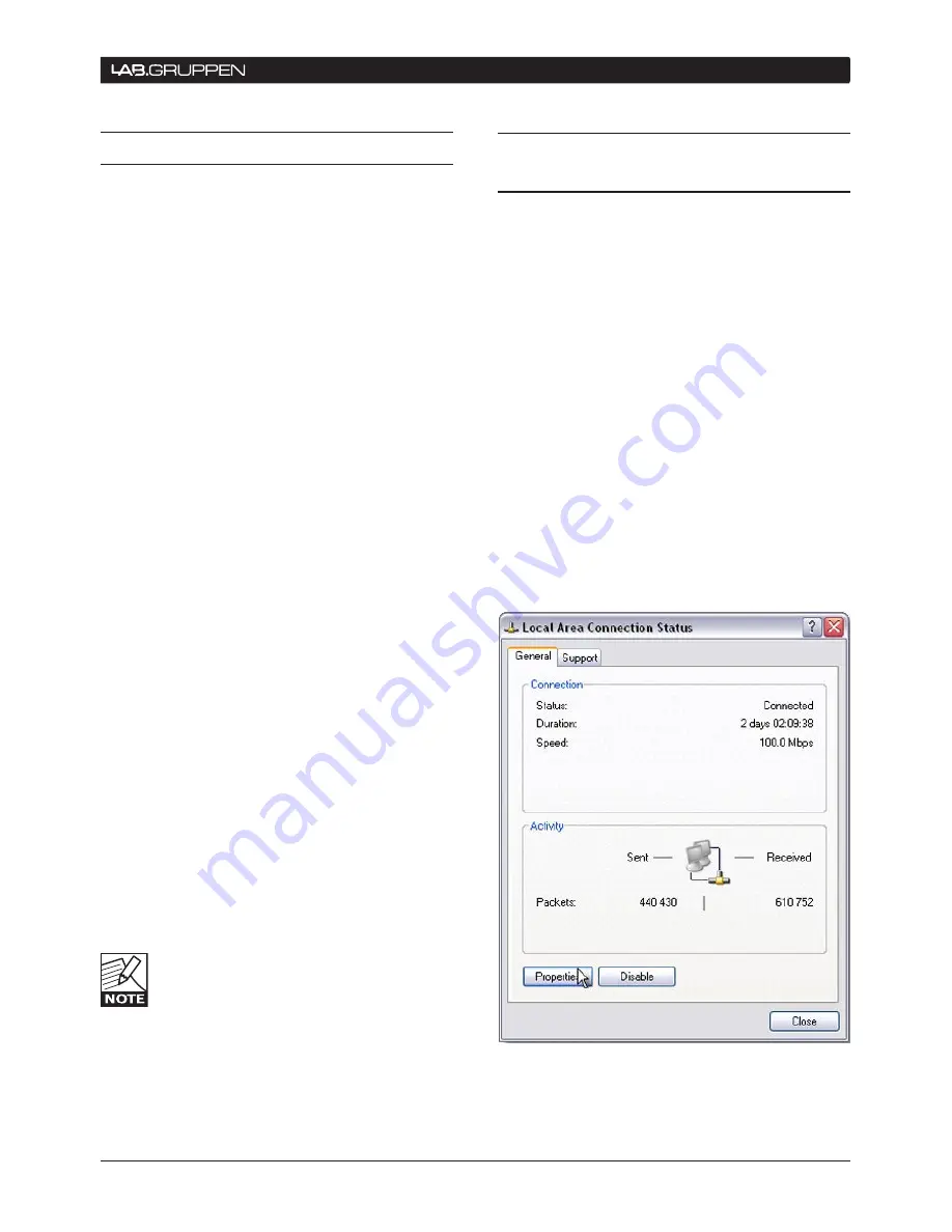
Change the IP address on the computer:

On your computer, go to Network connections, 

1. 

Local  Area  Connection  and  click  on  the 
Properties button.

APPenDIx  10

Summary of Contents for NLB 60E

Page 1: ...Rev 2 00 Operation manual Item no OM NLB60E NLB 60E NomadLink Bridge and Network Controller...

Page 2: ...duction and network requirements 12 7 1 2 Cable connections 12 7 1 3 Direct connection to PC peer to peer 12 7 1 4 Connection through Local Area Network LAN 12 7 2 TCP IP network setup instructions 12...

Page 3: ...l Purpose Input GPI settings 24 9 3 5 5 Power Sequence delay setting 25 9 3 5 6 Front panel PIN code lock setting 25 9 3 5 7 Display contrast adjust 25 9 3 5 8 Security 25 9 3 6 Subnet Info 25 9 3 7 S...

Page 4: ...d injury from tipping over Unplug this apparatus during lightning storms or when unused for long periods of time 13 Do not connect an amplifier output in parallel or series with any other amplifier s...

Page 5: ...EMC EMI This equipment has been tested and found to comply with the limits for a Class B Digital device pursuant to part 15 of the FCC rules These limits are designed to provide reasonable protection...

Page 6: ...software to detect devices that are not currently turned on or connected to the mains This ensures very high reliability and redundancy while at the same time allowing connected amplifiers to remain...

Page 7: ...ckaging 4 2 Mounting The NLB 60E is one rack unit high 1U and will fit into a standard EIA 19 rack The depth is 208mm 8 2 The weight is approximately 2 25 kg 5 lbs The NLB 60E may be mounted directly...

Page 8: ...T ADJUST SET EXIT ESC ENTER OK NomadLink Subnet Power ON OFF NomadLink and Ethernet activity LEDs RJ45 Ethernet connector Ethernet on EtherCon housed RJ45 for standard PC using TCP IP NomadLink networ...

Page 9: ...of the next amplifier until all amplifiers are connected Complete the network loop by connecting the OUT port of the last amplifier to the IN port on the NLB 60E The OUT port of the NLB 60E must be co...

Page 10: ...a single subnet up to 60 units are located at some distance from each other the following general rules should be considered On the right side are typical examples of how NomadLink network setups can...

Page 11: ...NLB 60E Operation Manual 11 CONNECTIONS TO AMPLIFIERS NOMADLINK 6...

Page 12: ...ct connection between the PC and the NLB 60E forms a peer to peer network In most cases this connection will require use of the crossed Ethernet cable A crossed connection is necessary because the NLB...

Page 13: ...er Using Windows XP as an example the following procedure will establish the proper IP settings 1 Go to START in lower left corner Select Connect to and Show all connections 2 Select Local Area Connec...

Page 14: ...on features and functionality of this software When DeviceControl is running and con nected to an NLB 60E the front panel keypad commands on the NLB 60E s will be locked out However GPI trigger com ma...

Page 15: ...Enabling of a secure connection is a two step process First the secure connection option must be enabled manually on each NBL 60E using the front panel keypad Then a password must be set in DeviceCont...

Page 16: ...Press Set d 8 Press OK in the Settings dialog Secure Connection is now enabled in the additional NLB 60E s You can verify that a secure connection has been enabled by checking the NLB 60E information...

Page 17: ...ore a new password can be entered The password also is reset when DeviceControl is uninstalled and reinstalled Entry of the old password is not required However depending on the Windows configuration...

Page 18: ...ss ENTER OK to access the next menu down or to confirm a selection Press EXIT ESC to access the next menu up in the command tree This allows you to escape a selection without changing settings Use the...

Page 19: ...information on this feature If an amplifier has been switched off locally and this was not the preconfigured status the NLB 60E will continue trying to switch it back on 9 2 4 Network LEDs and Ethern...

Page 20: ...rk and display Subnet numbers and the total number of devices found on the Subnet This view is the default Homepage that will appear after a period of system inactivity It is also the view that is dis...

Page 21: ...irmware version displays are provided for convenient review and to aid in technical support and troubleshooting The Serial Number is also displayed by a sticker on the rear panel of the NLB 60E The MA...

Page 22: ...e NLB 60E s rear panel The GPI 1 is a Voltage sensing input detecting states above and below 12V DC GPI 2 and GPI 3 are identical contact closure inputs that detect an open or closed state The GPI Sta...

Page 23: ...ar to what happens when the PC displays Obtain IP address automatically This requires that the functions of a DHCP server be available on the network Most standard network routers today offer this fun...

Page 24: ...own keys to select the desired action Disabled shows as a dash Low High Ok Mute High Low Ok Unmute When you have made your selection press OK The following display allows the opposite action to be set...

Page 25: ...om pensate for viewing angle and lighting conditions you may adjust the display s contrast Use up down arrow keys to make changes 9 3 5 8 Security Security Enter The Security configuration menu allows...

Page 26: ...he various faults If the number of faults is 0 and you press ENTER anyway this will take you to a display saying All ok When faults are indicated press ENTER to scroll through the list of faults using...

Page 27: ...vices Three different states are possible 1 Can t power ON NLB 60E is not able to power on the amplifier remotely No other fault can be Device 1 3 Can t power ON Device 1 5 Can t power OFF Device 1 5...

Page 28: ...the tree structure is organized for the various features The headlines Level 1 are displayed at the right followed by sub views with subsequent displays for level 2 3 and 4 10 appendix Unlock UI PIN...

Page 29: ...w Ok GPI2 Ok Mute Unmute Open Close Ok Close Open Ok GPI3 Ok Mute Unmute Security Enter Open Close Ok Secure conn Ok Enabled Reset password Ok Close Open Ok Secure conn Enable The password has been re...

Page 30: ...ice 1 60 Ser 122222222 Device 1 1 FW ver 1 00 Device 1 60 FW ver 1 02 Device 1 3 Can t power ON Device 1 5 Can t power OFF Subnet 1 Com errors XX Open loop 14 1 17 2 Open loop 14 2 NLB 60E Level 1 Lev...

Page 31: ...power off or 8 disconnect the Ethernet connection before you see the Succeeded to update window If you experience a failure in the update procedure due to loss of power or other unforeseen issues ple...

Page 32: ...operate the NLB 60E s front panel features A When a PC running DeviceControl is connected to the NLB 60E and thus directly controlling the NomadLink subnet all commands from the front panel and GPI c...

Page 33: ...character white text on blue background Yes x6 Yes x2 100 to 240 VAC 50 to 60 Hz auto select 35 W W 483 mm 19 H 44 mm 1 U D 208 mm 8 2 2 25 kg 5 lbs Black anodized aluminum front and painted steel ch...

Page 34: ...y loss due to cancellation of any events or rent of replace ment equipment or costs due to a third party s or customer s loss of profit or any other indirect cost or losses however incurred Lab gruppe...

Page 35: ...L a b g r u p p e n AB S w e d e n i n t e r n a t i o n a L c o n t a c t i n f o L a b g r u p p e n c o m U S CONTACT i n f o u s t c e l e c t r o n i c c o m w w w l a b g r u p p e n c o m...

Reviews: