NLB 60E Operation Manual
27
oPeRAtIon AnD conFIGURAtIon 9
A current fault indicates a problem with the NLB
60E’s phantom power supply to NomadLink.
If the Subnet contains cables that are too long or
are faulty, or if too many devices are connected,
this can cause excessive current draw and place
the NLB 60E in protection mode. You can fix the
problem by checking cables or removing devices.
Note: All amplifiers on the subnet will continue to
function in their current state should the NLB 60E
enter protection mode.
See Appendix for cable length and number
of devices on NomadLink network recom-
mendations.
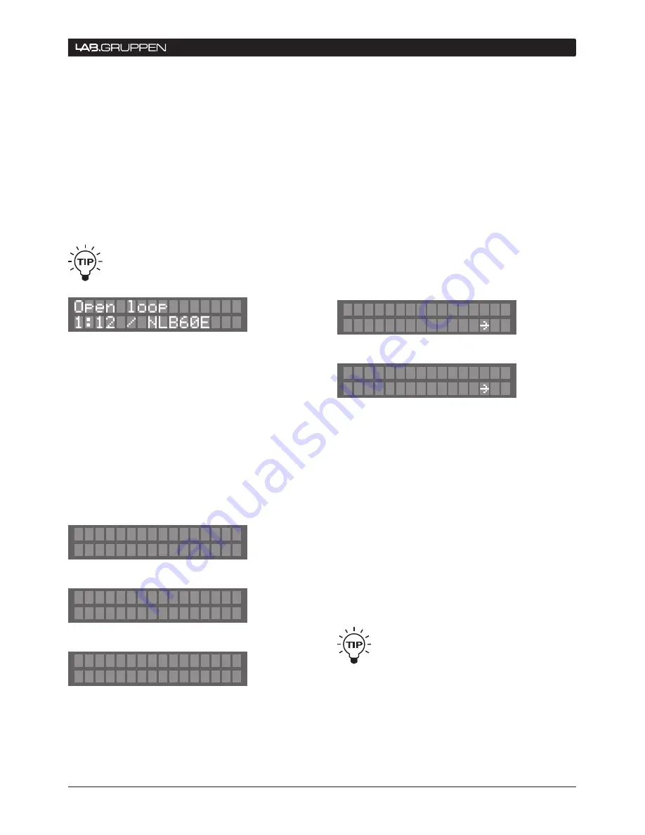
If the NLB 60E is configured as a Closed Loop, a fault
will be reported when an open loop is detected. The
information is displayed in one window as illustrated
in the example above. The first shown is the device
where the OUT port has been disconnected: Subnet
1, amplifier 12. The second device (here the NLB 60E)
is the device where the IN port has been discon-
nected. This feature makes it easy to determine the
location of any missing Closed Loop connection.
Following the display(s) for network specific faults,
remaining displays will indicate any current faults for
specific devices:
Three different states are possible:
1) Can’t power ON - NLB 60E is not able to power
on the amplifier remotely. No other fault can be
Device: 1.3
Can't power ON
Device: 1.5
Can't power OFF
Device: 1.5
Internal Fault
detected if this state is present.
2) Can’t power OFF - NLB 60E is not able to power
off the amplifier remotely. Fault #3 is still possible
to detect.
3) Internal fault - This can be one of several different
types of faults (e.g. temperature protection). For
detailed information, connect a PC to the NLB 60E
Ethernet port and use the DeviceControl application.
Fault #2 can be detected even when this fault is
present.
After scrolling through the fault displays, press ESC
to return to main menu.
9.3.8 Lock UI / Unlock UI
Press OK at the Lock UI display to disallow the
modification of parameters and settings from the
front-panel.
In this state, it is still possible to access and modify
settings using Ethernet and the DeviceControl appli-
cation. Also, any functions initiated by GPI commands
will continue to operate.
To unlock the UI, dial in the four-digit PIN-code. The
PIN is set under the Configuration displays. If no
PIN has been defined, it will not be possible to lock
the front-panel.
Default PIN is 0000, which will not lock the front-
panel.
It is also possible to unlock the UI by press-
ing and holding the ESC+OK buttons when
powering up the NLB 60E.
Lock UI?
Ok
Unlock UI?
PIN:**** Ok


