


LAARS Heating Systems
Page 8
linear run. Subtract 10 allowable linear feet (3.0m) for
every additional elbow used (see
Table 2
). When fewer
than 3 elbows are used, the maximum linear pipe
length allowed is still 50 feet (15.2m).
The connection for the intake air pipe is on the
filter box. Pennant appliances may have venting and
combustion air ducting attached to the top or the back.
They are shipped with the connections at the top. For
attaching either or both pipes to the back, the mounting
flanges are reversible by removing the mounting
screws and orienting the flanges in the desired
position. Replace the screws after positioning flanges.
Run a bead of silicone around the collar and slide the
pipe over the collar. Secure with sheet metal screws.
In addition to air needed for combustion, air
shall also be supplied for ventilation, including all air
required for comfort and proper working conditions
for personnel. The Pennant loses less than 1 percent of
its input rating to the room, but other heat sources may
be present.
2.2 Venting
2.2.1 Vent Categories
Depending upon desired Pennant venting, it may
be considered a Category I or a Category III appliance.
In general, a vertical vent system will be a Category
I system. However, in rare instances, a Pennant’s
vertical vent system may be considered Category
III. In the U.S., the National Fuel Gas Code (ANSI
Z223.1), or in Canada the Natural Gas and Propane
Installation Code (CSA B149.1), defines a Category I
vent system, and includes rules and tables to size these
vent systems. If the Pennant’s vertical vent system
does not satisfy the criteria for Category I venting, it
must be vented as a Category III system.
All Pennant vent systems which discharge
horizontally (without the use of a power venter) are
considered Category III vent systems.
2.2.2 Category I Vent
When vented as a Category I appliance, the
vent system must conform to the National Fuel Gas
Code (ANSI Z223.1-Latest Edition) in the U.S., or in
Canada, to the Natural Gas and Propane Installation
Code (CSA B149.1 latest edition). The vent system
must be sized and installed for a Category I Fan-
Assisted Appliance.
If chimney height is greater than 25 feet, or
if multiple units are vented into the same vertical
vent, a barometric damper must be installed on each
appliance, such that the flue draft does not exceed
(negative) 0.1 in. w.c.
If using a power venter for any type of Category
I venting, the draft should be set between (negative)
0.01 and 0.05 in. w.c.
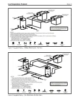
2.2.3 Common Venting Systems
Pennant units are Category I fan-assisted when
vented vertically and adhering to all applicable codes.
Pennant units are not allowed to be vented into a
common horizontal vent system, unless a properly
sized vent fan is used, and the common vent system
is properly designed by the vent fan manufacturer or
a qualified engineer. When common venting Pennant
fan-assisted unit with other appliances through
one shared vertical duct called a “common vent”,
special care must be taken by the installer to ensure
safe operation. In the event that the common vent
is blocked, it is possible, especially for fan-assisted
devices, to vent backwards through non-operating
appliances sharing the vent, allowing combustion
products to infiltrate occupied spaces.
If the
appliances are allowed to operate in this condition,
serious injury or death may occur.
WARNING
Operation of appliances with a blocked common
vent may lead to serious injury or death. Safety
devices must be implemented to prevent blocked
common vent operation. If safe operation of all
appliances connected to a common vent cannot
be assured, including prevention of spillage of flue
gasses into living spaces, common venting should
not be applied, and appliances should each be
vented separately.
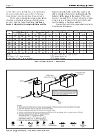
Figure 2. Combustion Air and Vent Through Roof.
Term
Description
Pipe
Single-wall galvanized steel pipe, 24 gauge
minimum (either insulated or non-insulated)
Joint Sealing Permanent duct tape or aluminum tape
Table 4. Required Combustion Air Piping Material.
Summary of Contents for Pennant PNCH
Page 23: ...Low Temperature Pennant Page 23 Figure 12 Ladder Diagram Sizes 500 1000 ...
Page 24: ...LAARS Heating Systems Page 24 Figure 13 Ladder Diagram Sizes 1250 2000 ...
Page 25: ...Low Temperature Pennant Page 25 Figure 14 Wiring Diagram Sizes 500 1000 ...
Page 26: ...LAARS Heating Systems Page 26 Figure 15 Wiring Diagram Sizes 1250 1500 ...
Page 27: ...Low Temperature Pennant Page 27 Figure 16 Wiring Diagram Sizes 1750 2000 ...


