


Low Temperature Pennant
Page 33
7.2.2 Filter
The filter used in the Pennant is washable. Since
the filter is washable, it will only need replacement
occasionally. If filter replacement is needed, it should
only be replaced with a factory part. Inspect the air
filter monthly, or more often in dirty environments. If
there is debris on the air filter, remove it from the filter
box, and wash it with mild soap and water. Ensure that
the filter is completely dry before reinstalling.
7.2.3 Gas Valves
The gas valves are designed to operate with
supply pressures of 4-13 inches w.c. (1.0 to 3.2 kPa).
To remove a valve, shut off 120-volt power
and the manual gas shutoff valve. Remove the top
front panel from the unit. Disconnect the wires to the
valve. Disengage the flanged fitting before and after
the valve, and remove the valve. Re-install in reverse
order. Ensure o-rings are properly installed for both
inlet and outlet. Turn on manual gas shutoff valve and
120 volt power and check appliance operation and
tightness of gas valve connections.
7.2.4 Manual Reset High Limit Control
The high limit switch is manual reset switch with
an adjustable set point, up to 240°F (116°C) on boiler
models and 200°F (93°C) on water heater models
and boilers ordered with low temperature controls. To
replace the switch, shut off the 120-volt power to the
appliance. Remove the cover from the switch to access
the mounting screws. Remove the screws, and pull
the switch off the control panel. Remove the capillary
and bulb from the thermal well located in the header.
Replace in reverse order.
7.2.5 Automatic Reset High Limit Control
An automatic reset high limit is used in addition
to the manual reset high limit. The high limit switch
has an adjustable set point, up to 240°F (116°C) on
boiler models and 200°F (93°C) water heater models
and boilers ordered with low temperature controls. To
replace the switch, shut off the 120-volt power to the
appliance. Remove the cover from the switch to access
the mounting screws. Remove the screws, and pull
the switch off the control panel. Remove the capillary
and bulb from the thermal well located in the header.
Replace in reverse order.
7.2.6 Temperature Control
The temperature control is an on/off control that
also manages the mixing system.
To replace the control, disable the 120v supply
power to the appliance. Unplug all of the electrical
connectors, remove the retainer clip and the control.
Replace the control in the reverse order.
7.2.7 Ignition Control
The ignition controls ensure the proved interrupt-
ed-type ignition system. They control the hot surface
ignitors and prove that the flame signal is appropri
-
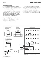
Figure 18. Typical Control Panel.
Summary of Contents for Pennant PNCH
Page 23: ...Low Temperature Pennant Page 23 Figure 12 Ladder Diagram Sizes 500 1000 ...
Page 24: ...LAARS Heating Systems Page 24 Figure 13 Ladder Diagram Sizes 1250 2000 ...
Page 25: ...Low Temperature Pennant Page 25 Figure 14 Wiring Diagram Sizes 500 1000 ...
Page 26: ...LAARS Heating Systems Page 26 Figure 15 Wiring Diagram Sizes 1250 1500 ...
Page 27: ...Low Temperature Pennant Page 27 Figure 16 Wiring Diagram Sizes 1750 2000 ...


