Laars NEOTHERM NTH Series Installation And Operation Instructions Manual Download Page 6

Page 6


LAARS Heating Systems

1.D  Safety Notes


WARNING

Carbon Monoxide Hazard

Improper adjustment of the burners may lead to poor 
combustion quality, increasing the amount of carbon 
monoxide produced. Excessive carbon monoxide 
levels may lead to personal injury or death.


WARNING

This unit must be installed in accordance with the 
procedures detailed in this manual, or the manufacturers 
warranty will be voided. The installation must conform 
to the requirements of the local jurisdiction having 
authority, and, in the United States, to the latest edition 
of the National Fuel Gas Code, ANSI Z223.1/NFPA54. 
In Canada, the installation must conform to the latest 
edition of  CSA B149.1 Natural Gas and Propane Gas 
Installation Code, and/or local codes. Where required 
by the authority having jurisdiction, the installation of 
these units must conform to the Standard for Controls 
and Safety Devices for Automatically Fired Boilers, 

ANSI/ASME CSD-1. Any modifi cations to the boiler, its 

gas controls, or wiring may void the warranty. If fi eld 

conditions require modifi cations, consult the factory 

representative before initiating such modifi cations.
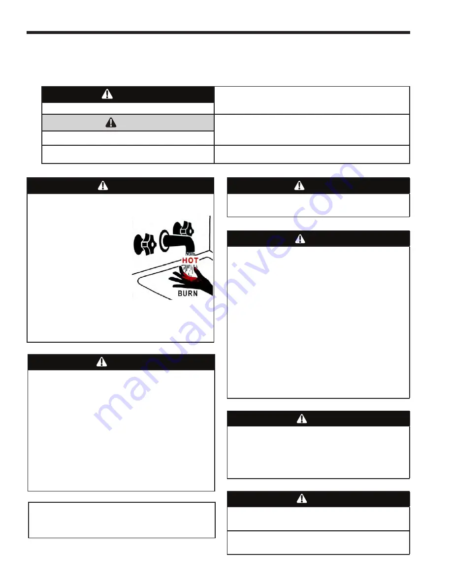
 

WARNING

•   Water temperature over 125°F (52°C) can cause 

severe burns instantly or death from scalds.

•   Children, disabled and 

elderly are at highest 
risk of being scalded.

•   See instruction manual

before setting temperature
at the unit.

•   Feel water before bathing

or showering.

•   If this unit is used

to produce water that could scald if too hot, such 
as domestic hot water use, adjust the outlet control 
(limit) or use temperature limiting valves to obtain a 
maximum water temperature of 125°F (52°C).


WARNING

The inlet gas pressure to the unit must not 

exceed 13” W.C. (3.2kPa).


WARNING

Fire or Explosion Hazard

Improper confi guration can cause fuel buildup and 

explosion. Improper user operation may result in 
property loss, severe physical injury, or death.

Any changes to safety-related confi guration 

parameters must only be done by experienced and/or 
licensed burner/boiler operators and mechanics.

If any odor of gas is detected, or if the gas burner does 
not appear to be functioning in a normal manner, close 

the main gas shutoff  valve.  Do not shut off  the power 

switch. Contact your heating contractor, gas company, 
or factory representative.

NOTE: This unit is protected against hydronic 
over-pressurization.  A pressure relief valve is included 
with each unit. 


WARNING

Indicates an imminently hazardous situation which, if not 
avoided, can or will result in death or serious injury and can 
or will result in catastrophic property damage. 

 CAUTION

Indicates a potentially hazardous situation which, if not avoided, 
may result in moderate injury and/or property damage. 

    NOTE:

Indicates instructions that are important to that topic but not 
related to personal injury or property damage. 

Safety Notes are used thoughout this manual to bring attention to the presence of hazards with various risk 

levels and to off er important information concering the life of this product. There are 3 basic types.  


WARNING

CANCER AND REPRODUCTIVE HARM. 

WWW.P65WARNINGS.CA.GOV.  

AS REQUIRED BY THE STATE OF 

CALIFORNIA PROPOSITION 65.

1

2

3

Summary of Contents for NEOTHERM NTH Series

Page 1: ...fire department Installation and service must be performed by a qualified installer service agency or gas supplier AVERTISSEMENT Assurez vous de bien suivres les instructions donn es dans cette notic...

Page 2: ...te Drain 23 6 D Freeze Protection 23 6 E Recognized Chemicals 23 6 F Suggested Piping Schematics 24 30 SECTION 7 ELECTRICAL AND WIRING DIAGRAMS 7 A Installation Warnings 31 7 B Main Power Connections...

Page 3: ...ponent Description 56 10 C Gas Conversion 58 SECTION 11 OPERATING DETAILS AND TROUBLESHOOTING 11 A Normal Startup and Initialization 60 11 B Sequence of Operation 60 11 C Modulation Control 60 11 D Pu...

Page 4: ...LAARS Heating Systems...

Page 5: ...input 2 1 0 210 000 BTU hr input 7 Fuel N Natural Gas P LP Gas 8 Options Code X U S C Canada 9 Pump Options N Pump included X No pump configuration available for all sizes 10 Revision 3 Third version...

Page 6: ...o hot such as domestic hot water use adjust the outlet control limit or use temperature limiting valves to obtain a maximum water temperature of 125 F 52 C WARNING The inlet gas pressure to the unit m...

Page 7: ...turbed as a result of servicing or repair these substances become airborne and if inhaled may be hazardous to your health Do not remove or replace RCF parts or attempt any service or repair work invol...

Page 8: ...AIR GAS BLOWER PRESSURE RELIEF VALVE WATER INLET WATER OUTLET AIR INLET CONNECTION DRAIN VALVE CONDENSATE TRAP AIR TRANSITION EXHAUST VENT CONNECTION GAS CONNECTION AIR PRESSURE SWITCH USER CONTROL I...

Page 9: ...L AIR INLET VENT IN CM IN CM IN CM 19 49 2 5 1 2 5 1 19 49 2 5 1 2 5 1 19 49 3 7 6 3 7 6 26 68 3 7 6 3 7 6 A B D E F G J Size in cm in cm in cm in cm in cm in cm in cm 80 13 34 9 24 7 19 10 28 11 30 1...

Page 10: ...Figure 3 1 Temperature pressure gauge kit 2 Air intake terminal 3 Exhaust vent terminal US only 4 Jumper Terminal 5 CPVC exhaust pipe section US only 6 Alternate size vent terminal screens 7 Outdoor...

Page 11: ...e Wall or Roof Termination The forced draft combustion air blower in the unit has sufficient power to vent properly when the guidelines in Table 3 are followed NOTE When located on the same wall this...

Page 12: ...12 xPPS VKL 5 xPPS VTML 5 8 83x050 2ZDESx Air Inlet 2ZDESx MFR MODEL NUMBER ABBREVIATED MFR MODEL NUMBER ABBREVIATED Trade Name Model Example Components Example Components Trade Name Model Boilers mus...

Page 13: ...tal ducts each opening shall have a minimum free area of not less than 1square inch per 2000 Btu hr 1100 square mm kW of total input rating of all equipment in the enclosure Method 2 One permanent ope...

Page 14: ...t can terminate through the roof or through an outside wall When using PVC CPVC for vent material venting must be connected to the CPVC section included with unit sizes 80 210 The CPVC vent section in...

Page 15: ...terminal must be installed If an exhaust vent terminal is not available with the certified vent system the Manufacturer suggests the use of a coupler fitting from the certified vent system into which...

Page 16: ...l so that it cannot be blocked by snow The National Fuel Gas Code requires that it be at least 12 inches 30cm above grade but the installer may determine it should be higher depending upon local condi...

Page 17: ...ulator vent outlet See note 4 3 feet 91 cm J Clearance to nonmechanical air supply Direct vent only 12 30cm 80 285 inlet to building or the combustion air inlet Other than Direct vent 4 ft 1 2m below...

Page 18: ...carbon monoxide detectors a In the event that the side wall horizontally vented gas fueled equipment is installed in a crawl space or an attic the hard wired carbon monoxide with alarm and battery ba...

Page 19: ...rs and any other gas burning appliance to their previous conditions of use 7 Any improper operation of the common venting system should be corrected so that the installation conforms to the National F...

Page 20: ...CTION 5 PUMP REQUIREMENTS 5 A Boiler Flow and Head Requirements Table 12 Water Flow Requirements Notes Consult and confirm with Applicable Fuel Gas Code before beginning work Verify gas inlet pressure...

Page 21: ...measured at the supply pressure port on the gas valve Low gas pressure could be an indication of an undersized gas meter undersized gas supply lines and or an obstructed gas supply line Some Units are...

Page 22: ...of boiler installation BOILER PIPE SIZE SIZE INCHES 80 1 105 1 150 1 210 1 Table 14 Water Connection Pipe Sizes SECTION 6 WATER CONNECTIONS 6 A Boiler System Piping Hot Supply Connections NOTE This u...

Page 23: ...ich may result in bursting of pipes or damage to the boiler which could result in leaking or flooding conditions Do not use automotive antifreeze To help prevent freezing Manufacturer recommends the u...

Page 24: ...Page 24 LAARS Heating Systems Figure 9 Hydronic Piping Single Boiler Zoning with Circulators...

Page 25: ...Page 25 NEOTHERM Residential Boilers Figure 10 Hydronic Piping Single Boiler Low Temp Radiant Space Heating Using Low Loss Header and Zone Valves...

Page 26: ...Page 26 LAARS Heating Systems Figure 11 Hydronic Piping Multiple Boilers Zoning with Circulators...

Page 27: ...Page 27 NEOTHERM Residential Boilers Figure 12 Hydronic Piping Multiple Boilers with Indirect DHW Tank Piped from System Loop...

Page 28: ...Page 28 LAARS Heating Systems Figure 13 Hydronic Piping Multiple Boilers Reverse Return Multi Temp Zones Zoning with Circulators...

Page 29: ...Page 29 NEOTHERM Residential Boilers Figure 14 Hydronic Piping Heating Zones with Indirect DHW Tank Piped with Zone Pumps The indirect DHW tank is piped directly off of the boiler...

Page 30: ...Page 30 LAARS Heating Systems Figure 15 Hydronic Piping Multiple Boilers with Indirect DHW Off of One Boiler The indirect DHW tank is piped directly off of the boiler...

Page 31: ...isolation or unless otherwise instructed by procedures outlined in this manual To signal a call for heat use the 24V field interlock as shown in the wiring diagram DO NOT MAKE AND BREAK THE LINE VOLTA...

Page 32: ...ommon settings used in a typical installation If your installation is more complex refer to Section 8C To reach the Quick Start menu press the I button Info Install then press the Quick Start menu ite...

Page 33: ...Page 33 NEOTHERM Residential Boilers Figure 16 Control Panel Layout...

Page 34: ...tions 7 F Lead Lag Connections These boilers can be connected in a lead lag series up to a total of 8 residential Units One as the Lead control and 7 more as the following controllers For general info...

Page 35: ...olled and monitored using a BAS Building Automation Systems control but only if one of the EMEA User Interfaces is replaced with the available color touchscreen Call your Manufacturers Representative...

Page 36: ...R GR VT GY R WH R GN TO J6 2 Y TO J4 10 OUTDOOR TEMP SENSOR TO GAS VALVE P1 1 2 2 1 6 1 6 1 6 1 Y WH GR TB6 FIELD CONNECTIONS ALARM TO J6 7 TO J6 8 BL BL Y OR BLK WH GY WH OR ALARM DHW TEMP SENSOR BLK...

Page 37: ...WH R WH R LTGN FS 1 DKB Y PK R BLK WH GN GR R WH CL CL CL CL CL WH R GN TN BRN OR TN BL TN R Y GY BL VT WH WH BLK BLK BLK TO XFORMER WH TO XFORMER WH R BRN WH BRN R Y PUR PUR BLK TN Y TN WH TN BLK WH...

Page 38: ...Page 38 LAARS Heating Systems Figure 19 Ladder Diagram 7 H Ladder Diagram...

Page 39: ...his is not the same as the round OK button the two have different functions Note This user interface is also referred to as the EMEA Display Videos are available online Figure 20 The User Interface SE...

Page 40: ...play Repeat this step for the other parameters if desired 8 E Entering Changing Control Settings Info Install Display including PASSWORDS The Info Install Display is where you will start every time Al...

Page 41: ...option to adjust the contrast of the display or change the items which appear at the top of the Home display See the section on Display Setup Table 17 Functions on Info Install Menu Press the round OK...

Page 42: ...me diagnostic and troubleshooting functions The installer level password is lnt lower case LNT OEM Level Some of the settings can only be changed at the Manufacturer factory Once you enter a password...

Page 43: ...to enter the new value Changing the DHW Domestic Hot Water Setpoint See the procedure described above for the CH setpoint Changing a Value Using a Slider There is another type of control screen that...

Page 44: ...then connected to terminal blocks 3 and 4 TB3 and TB4 See Figure 30 8 H Hydronic Heating Demand When using the unit for hydronic heating a call for heat must be supplied to the T T or Interlock termi...

Page 45: ...s of the outdoor temperature The line in the graph would run straight across the display However with the Outdoor Reset feature turned on the system will adjust for changes in the outdoor temperature...

Page 46: ...I to go to Info Install Choose Advanced Setup then go to Lead Lag Configuration Select Lead Lag Outdoor Reset Set the value on the line for Min Outdoor Temp 4 Set the low water temperature If the out...

Page 47: ...ter DHW as a stand alone volume unit DHW models or as a secondary function while the unit also provides hydronic heating The piping used to supply domestic hot water DHW can be set up in several diffe...

Page 48: ...an also be 0 10Vdc using a converter When setting up a sys tem using an external control take care to set Anti Short Cycle feature to prevent hunting and possible premature component failure Boiler Pu...

Page 49: ...n rates of all of the operating boilers Lead Lag Modulation Cycle Note We will explain the modulation cycle here in case you need to understand how the Lead Lag system actually operates If you are ins...

Page 50: ...of these addresses The unit operating as the Lead Lag Master should have address 1 and the other boilers should each have unique Modbus address numbers CAUTION You should set the Modbus addresses bef...

Page 51: ...change the firing order of the boilers based on the run time of each burner identify each unit as a Follower by turning on Follower Enable How to get there From the Home screen press I to go to Info I...

Page 52: ...Home screen press I to go to Info Install Choose Test then go to Forced Rate Select Set High Fire then select Start Test The CO2 readings should be between the values shown in Table 19 If the CO2 is n...

Page 53: ...setting The Gas Valve in the 80 thru 210 is at the front of the unit and can be reached after the front panel is pulled forward and then off Always be patient with your combustion analyzer when making...

Page 54: ...rt has been under water Manufacturer requires boilers to be replaced not repaired if they have been partially or completely submerged SECTION 9 FIRST START UP AND ADJUSTMENT INSTRUCTIONS 9 A Filling t...

Page 55: ...the post purge cycle One or three additional attempts to light will follow Each cycle will include pre purge ignitor on valve flame on and post purge Ignition will not occur because the gas is off Th...

Page 56: ...life and dependable operation but the safety of equipment depends on their proper functioning Only a qualified service technician should inspect the basic items listed below every year a Unit controls...

Page 57: ...in gas supply line Remove the front door of the boiler to gain access to the flame sensor electrode Remove the flame sensor wire from the electrode Remove the two bolts fastening the electrode to the...

Page 58: ...uired maintenance lack of water flow or improper operating practices WARNING Failure to rinse the debris from the heat exchanger and temporary drain line may lead to clogged condensate lines traps and...

Page 59: ...l Boilers size mbtu Kit number 80 CA006201 105 CA006202 150 CA006203 210 CA006204 Table 20 Propane Gas Conversion Kits size mbtu Kit number 80 CA006206 105 CA006206 150 CA006206 210 CA006206 Table 21...

Page 60: ...trol will lockout with a 109 error code 7 The call for heat signal is removed 8 The gas valve shuts off 9 The fan and pump continue to run for the over run times to purge the system This is the basic...

Page 61: ...temperature rise delta T is calculated using the inputs from the outlet and inlet sensor temperatures Stack Limit The stack temperature is sensed by a dual thermistor sensor and is limit rated The co...

Page 62: ...n 12 Front Bezel R50D7121 R50D7121 R50D7121 R50D7121 13 Display mounting frame R50D7122 R50D7122 R50D7122 R50D7122 12 13 Complete Assembly R50D7120 R50D7120 R50D7120 R50D7120 Internal Components See F...

Page 63: ...Water Temp SensorRE2320600 RE2320600 RE2320600 RE2320600 64 Duplex Outlet Water RE2319900 RE2319900 RE2319900 RE2319900 Temperature Sensor 65 Duplex Stack RE2319700 RE2319700 RE2319700 RE2319700 Temp...

Page 64: ...108700 RE2108700 RE2108700 RE2108700 82 High Voltage Shield R50D7002 R50D7002 R50D7002 R50D7002 83 Top Panel Bracket R50D7003 R50D7003 R50D7003 R50D7003 84 Electronic Control Contact Customer Service...

Page 65: ...Page 65 NEOTHERM Residential Boilers Figure 41 Jacket Components Optional Touchscreen User Interface Kit KM50D7130 Call your local Manufacturers Rep...

Page 66: ...Page 66 LAARS Heating Systems Figure 42 Gas Train Components Sizes 80 210 Figure 43 Internal Components Sizes 80 210...

Page 67: ...Page 67 NEOTHERM Residential Boilers Figure 44 Heat Exchanger Components 68A 65 67 60 66 63 64...

Page 68: ...Page 68 LAARS Heating Systems Figure 45 Electrical Components...

Page 69: ...nual Pump Operation Info Advanced Setup System Config Pump Config Boiler pump cycle count Y A new value can be written here if the pump or controller is replaced Info Advanced Setup System Config Stat...

Page 70: ...nfiguration I gain LL Y When using the Lead Lag system to control multiple boilers This gain is applied to the Integral term of the PID equation for the hydronic heating loop Info Advanced Setup Lead...

Page 71: ...system will use the normal CH setpoint Quick Start Info Advanced Setup CH Configuration Outdoor Reset Config Min outdoor temp LL When using the Lead Lag system to control multiple boilers with Outdoor...

Page 72: ...steresis value normally about 10 F Info Advanced Setup Lead Lag Configuration LL Master Config Outdoor reset CH Enable Outdoor Reset feature turned on Quick Start Info Advanced Setup CH Configuration...

Page 73: ...Lead Lag Master to supervise the Lead Lag system The controllers on all of the other boilers must be enabled as Followers See the section on About Lead Lag The choices are Disable Enable via Modbus Ma...

Page 74: ...erification L 1 Device in Configuration mode and safety parameters need verification and a device needs reset to complete verification 2 Configuration ended without verification re enter configuration...

Page 75: ...ing flame sensing time H 26 Internal fault Static flame ripple H 27 Internal fault Flame rod shorted to ground detected H 28 Internal fault A D linearity test fails H 29 Internal fault Flame bias cann...

Page 76: ...wer at Terminal Block 8 TB8 for the Safety Chain components See Figure 16 on page 33 3 Check wiring and correct any faults 4 Check all safety interlocks connected to the safety circuit to assure prope...

Page 77: ...Domestic Hot Water sensor fault H 1 Check wiring and correct any possible errors 2 Replace the DHW sensor 3 If previous steps are correct and fault persists replace the module 94 Header sensor fault...

Page 78: ...iled L 1 Check wiring and correct any potential wiring errors 2 Check VFD s Variable speed Fan Drive ability to change speeds 3 Change the VFD 4 If the fault persists replace the module 123 Purge rate...

Page 79: ...sists replace the module 160 Ignition On L 1 Check Ignition terminal wiring and correct any errors 2 Reset and sequence the module If fault persists replace the module 161 Ignition Off L 1 Check the i...

Page 80: ...sensor type setting L 192 Invalid igniter on during setting L 193 Invalid ignite failure delay setting L 194 Invalid ignite failure response setting L 195 Invalid ignite failure retries setting L 196...

Page 81: ...ing L 221 Unconfigured DHW Domestic Hot Water high limit setpoint setting L 222 Unconfigured Outlet high limit setpoint setting L 223 Unconfigured Stack limit setpoint setting L 224 Invalid DHW Domest...

Page 82: ...LAARS Heating Systems Notes...

Page 83: ...NEOTHERM Residential Boilers Notes...

Page 84: ...00 Fax 905 636 0666 www Laars com Litho in U S A Laars Heating Systems 20 04 Document 1252G Notes Dimensions and specifications subject to change without notice in accordance with our policy of contin...

Reviews: