background image

Page 15


b. 

Drinking of alcoholic beverages 
before or during spa or hot tub use can 
cause drowsiness which could lead to 
unconsciousness and subsequently result in 
drowning.


c. 

Pregnant women beware! Soaking in water 
above 102°F (39°C) can cause fetal damage 

during the first three months of pregnancy 

(resulting in the birth of a brain-damaged or 
deformed child). Pregnant women should 
stick to the 100°F (38°C) maximum rule.


d. 

Before entering the spa or hot tub, users 
should check the water temperature with 
an accurate thermometer; spa or hot tub 
thermostats may err in regulating water 
temperatures by as much as four degrees 
Fahrenheit (2.2°C).


e. 

Persons with a medical history of heart 
disease, circulatory problems, diabetes or 
blood pressure problems should obtain their 
physician's advice before using spas or hot 
tubs.


f. 

Persons taking medications which 
induce drowsiness, such as tranquilizers, 
antihistamines or anticoagulants, should not 
use spas or hot tubs.

SECTION 4.
Maintenance

1.  Inspect the pump seal every 6 months. Replace the 

pump if the seal shows signs of leakage or wear.

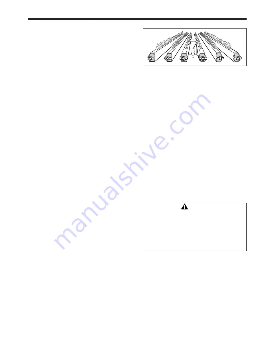
2.  At start-up and every six (6) months thereafter, the 

pilot and main burner flame should be observed 

for proper performance (see Figure 16). See 
attached lighting and shut-down instructions 

for proper pilot flame pattern. If flame has the 

appearance of "sooting" tips, check for debris near 

orifices and call a qualified service technician. 

3.  Inspect the venting system for obstruction, leakage 

and corrosion at least once each year.

4.  Keep heater area clear and free from combustible 

material, gasoline and other flammable vapors and 

liquids (see Table 1 for minimum clearances).

5.  Be certain all combustion air and ventilation 

openings in the room are unobstructed.

6.  Check for fouling on the external surfaces of 

the heat exchanger every six months. (

NOTE:


after installation and first start-up, check the heat 

exchanger for fouling after the following periods 

of operation: 24 hours, 7 days, 30 days, 90 days 

and once every six months thereafter.)


Fouling on the external surfaces of the heat 
exchanger is caused by incomplete combustion 
and is a sign of combustion air and/or venting 
problems. As soon as any fouling is observed, 

Figure 16. Main Burner Flame Pattern.

the cause of the fouling should be corrected (see 
Section 5, Troubleshooting Guide). The heat 

exchanger can be checked with a flashlight by 

locating a mirror under the burners. An alternate 
method is to remove the venting and top panels 
as necessary to inspect the heat exchanger from 
above. Also check the vent system for defects 

at this time. (If cleaning is required, shut off all 

electrical and gas supply to the heater.)

7.  To expose the heat exchanger:


Indoor Models:

 Remove the flue pipe, top of unit, 

rear upper jacket, flue collector rear panel and heat 

exchanger baffles.


Outdoor Models:

 Remove vent top assembly, 

rear upper jacket, flue collector rear panel and heat 

exchanger baffles.

8.  To remove all burners:


It is usually more convenient to remove the burner 
tray assembly. Disconnect sensor wire, ignition 
cable (or thermocouple generator) and pilot gas 
line. Disconnect manifold inlet union(s). Remove 
the four (4) retaining screws. Grasp the manifold 
pipe and slide out the burner tray.

Caution

      Black carbon or green soot on a dirty heat 

exchanger can, under certain conditions, be 

ignited by a random spark or open flame. To 

prevent this unlikely occurrence, dampen the 

soot deposits with wet brush or fine water 

spray before servicing or cleaning the heat 

exchanger.

9.  Clean heat exchanger using a wire brush to 

remove soot and loose scale from the unit. Clean 
fallen debris from bottom of heater. Make sure 
burner ports are clear and pilot assembly is free of 
debris.

10.  Reassemble in reverse order and be sure the heat 

exchanger baffles are replaced.

11.  The gas and electric controls installed on the 

heater are engineered for both dependable 
operation and long life, but the proper 
functioning of these components is necessary 
for safe operation of the heater. It is strongly 
recommended that the basic items be checked by 
a competent serviceman every year and replaced 

MightyTherm Pool Heater

Summary of Contents for Mighty Therm AP

Page 1: ...pas tenter d allumer d appareils Ne touchez aucun interrupteur Ne pas vous servir des t l phones dansle b timent o vous vous trouvez Appelez imm diatement votre fournisseur de gaz depuis un voisin Su...

Page 2: ...or Pool Heaters 7 2 4 Gas Supply and Piping 7 2 5 Electrical Wiring 8 2 6 General Piping Instructions 9 2 7 Heater By Pass Piping 9 2 8 Temperature Sensor Placement and Installation 10 2 9 Automatic C...

Page 3: ...N HEAT EXCHANGER C GLASS LINED COPPER N GLASS LINED CU NI A GLASS LINED COPR REVRSD M GLASS LINED CU NI REVRSD Option Code XX Standard JX CSD 1 HL High low gas pressure switches LC LWCO 100 lockout LW...

Page 4: ...of ANSI standard Z223 1 and any local codes that may be applicable Inadequate combustion air supply may result in incomplete combustion sooting of the heat exchanger and unsafe operation of the heate...

Page 5: ...and must not be connected to any portion of a mechanical draft system under positive pressure The flue outlet must be connected to a clear unobstructed vent of adequate capacity ending above the high...

Page 6: ...ing system are located and the other spaces of the building Turn on any clothes dryer and any appliance not connected to the common venting system Turn on any exhaust fans including range hoods and ba...

Page 7: ...or wall recess Avoid locations where wind deflection off structures might cause downdraft When such wind conditions are possible place the heater at least 3 feet 0 9m from the structures 3 Never insta...

Page 8: ...cifically ordered otherwise 2 The 1825 models are supplied with 3 4 HP pump motors All other models are supplied with 1 2 HP pump motors Consult the National Electrical Code or the Canadian Electrical...

Page 9: ...ilter system are made of plastic materials they may be damaged by the momentary back siphoning of hot water from the heater when the filter pump stops running The pressure relief valve installed in th...

Page 10: ...Controls a Intermittent Ignition Pilots are automatically lit when the operating control calls for heat Systems 4 9 and 11 The unit performs its own safety check and opens the main valves only after...

Page 11: ...e auto reset limit switch is provided as standard equipment on all heaters The temperature sensing bulb of the switch is field installed and should be located in the pool loop piping See Section 2 8 f...

Page 12: ...auses air to be drawn into the heater and the secondary piping an automatic float type air vent should be permanently installed on top of the pump scroll 3 To check the heater firing proceed as follow...

Page 13: ...pen throttle turn down outlet valve B slightly Observe the inlet thermometer for 5 minutes to see where the inlet temperature stabilizes If it remains under 110 F 43 C throttle outlet valve B a little...

Page 14: ...caution is suggested for young children adjusted incrementally to obtain the desired pool operating temperature 7 An adjustable pump time delay relay is mounted in the control panel see Figure 11 Thi...

Page 15: ...30 days 90 days and once every six months thereafter Fouling on the external surfaces of the heat exchanger is caused by incomplete combustion and is a sign of combustion air and or venting problems...

Page 16: ...operating condition and preventing corrosion liming or other problems Proper pool water chemistry includes other values that must be maintained for swimmer safety Refer to your local agency having jur...

Page 17: ...r u s s e r p m o r f y r a s s e c e n s a t s u j d a F Electric gas valve operator is F Disconnect wiring harness at gas valve terminals Check continuity of actuator burned out or shorted coil If o...

Page 18: ...303 10548301 14 Tile Heat Shield Spacer Rear 10548401 10548402 10548403 10548404 15 Saddle Assembly End Tile 10533600 10533600 10533600 10533600 10533600 10533600 10533600 10533600 10533600 2 2 2 2 2...

Page 19: ...Page 19 Figure 17 Parts Identification Mighty Therm Commercial Pool Heating Boiler Page 19 Figure 17 Parts Identi cation ONE PIECE PUMP VOLUTE MightyTherm Pool Heater...

Page 20: ...n Combustible Base Rail 10539000 10539000 10539000 10539000 10539000 10539000 10539000 10539000 10539000 2 2 2 2 2 2 2 2 2 Water System 34 8 Tube Assembly Copper Tubes 10534701 10534702 10534703 10534...

Page 21: ...101 2 2 2 2 2 2 2 2 2 42 Flange Gasket S0063700 S0063700 S0063700 S0063700 S0063700 S0063700 S0063700 S0063700 S0063700 2 2 2 2 2 2 2 2 2 43 Header Gasket w Barrier S0095100 S0095100 S0095100 S0095100...

Page 22: ...00 58 Pilot Bracket Burner Weldment 10529502 10529502 10529502 10529502 10529502 10529502 10529502 10529502 10529502 59 Pilot Burner W0035800 W0035800 W0035800 W0035800 W0035800 W0035800 W0035800 W003...

Page 23: ...Control Electronic E2305400 E2305400 E2305400 E2305400 E2305400 E2305400 E2305400 E2305400 E2305400 Single Try 72 Transformer 115V 24V R0021300 R0021300 R0021300 R0021300 R0021300 R0021300 R0021300 R0...

Page 24: ...ssemblies When ordering tiles Assembly number is for all tiles Part numbers shown for the front of unit are the same for the rear tiles Check dimensions of old tile as shown here to confirm part numbe...

Page 25: ...Page 25 Figure 19 Outdoor Parts 1 2 3 4 5 6 7 8 9 10 11 12 14 15 16 17 18 19 13 20 MightyTherm Pool Heater...

Page 26: ...10665907 10665908 10665909 Copper Tube Cast Iron Tubs Outdoor 10 Tube Assembly 20001101 20001102 20001103 20001104 20001105 20001106 20001107 20001108 20001109 Copper Tube Bronze Tubs Outdoor 10 Tube...

Page 27: ...Front End Panel 10657501 10657501 10657501 10657501 10657501 10657501 10657501 10657501 10657501 13 Right Front End Panel 10657502 10657502 10657502 10657502 10657502 10657502 10657502 10657502 10657...

Page 28: ...905 636 0666 www Laars com Litho in U S A Laars Heating Systems 21 10 Document 3006V Laars Heating Systems Company reserves the right to change specifications components features or to discontinue pro...

Reviews: