Page 10
The well should be installed just downstream
of the heater outlet tee. DO NOT INSTALL the
bulb in the heater loop piping or upstream of the
heater outlet tee.
5.
Route the capillary tube in a location where it will
not be subject to damage. Secure with wire ties.
2.9 Automatic Chlorinators
A concentration of chlorine in the heater can be
very destructive, therefor the following rules about
the installation and operation of such devices must be
followed:
1.
The chlorinator should be installed so it
introduces the gas or solution downstream from
the heater.
2.
The chlorinator should be wired so it cannot
operate unless the filter pump is running.
3.
The chlorinator should be provided with an anti-
siphon device so that the draining of the piping
after the pump shuts off will not siphon chlorine
solution into the heater.
4.
When the operation of a chlorinator is such
that it must be installed in the pump suction, or
some other place where the chlorine solution
flows through the heater, corrosion of the heater
can occur. Excessive concentrations of chlorine
caused by improper adjustment or failure of the
chlorination equipment cause this corrosion. The
resulting damage to the heat exchanger is not
covered by heater warranty.
SECTION 3.
Operation
3.1 Controls - General
(see Figures 11 and 12)
1. Electronic Ignition Controls:
a. Intermittent Ignition:
Pilots are automatically lit when the
operating control calls for heat (Systems
#4, #9 and #11). The unit performs its own
safety check and opens the main valves
only after the pilot is proven to be lit.
Whenever the pilot flame is interrupted, the
main gas valve closes within 0.8 seconds.
b.
Electronically Supervised Standing Pilot
System (System #16):
When pilot flame fails, the ignition control
module responds in less than 0.8 seconds
and provides 100% safety shutdown.
2. Operating Controls:
An electronic temperature control is provided
Heater Model
Minimum Filter Pump Flow Rate
500-850
90 GPM
1010 -1200
110 GPM
1430
140 GPM
1670-1825
180 GPM
Table 4. Minimum Flow to Supply Heater Loop.
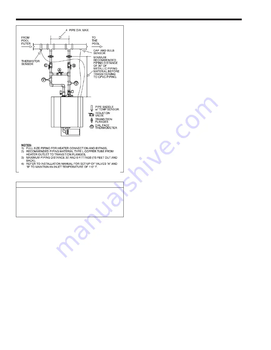
2.8 Temperature Sensor Placement
and Installation
Two temperature sensing devices are installed on the
heater that require sensing bulbs be field installed
according to Figure 10.
1.
Install the thermistor based sensor's immersion
well on the underside of the pool loop piping.
The well should be installed just upstream of
the heater inlet tee. DO NOT INSTALL the bulb
in the heater loop piping or down stream of the
heater outlet tee.
2.
Thread the spring and retainer onto the sensor
cable and secure sensor into the immersion well.
3.
Route cable to heater control panel in a location
where it will not be subject to damage. Secure
with nylon cable ties.
4.
Install the capillary tube/bulb sensor immersion
well on the underside of the pool loop piping.
Figure 10. Heater Piping Arrangement.
LAARS Heating Systems


