


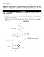

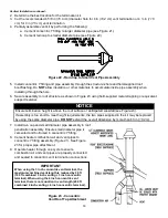


25
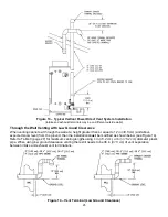
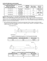
Figure 13
– Typical Vertical Power Direct Vent System Installation
(Intake and exhaust terminals may be on different outside walls
)
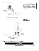
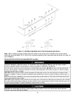
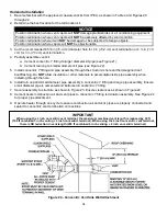
Through the Wall Venting with Low Ground Clearance
When venting cannot exit through the wall at a height greater than or equal to 12 in
(30.5 cm)
(and above
expected snow level) from the ground, then the installation
must
be modified as shown below (see Figure 14).
Refer to Table 3 (page 27) for maximum venting lengths using 4 in
(10.2 cm),
or 6 in
(15.2 cm)
diameter
plastic
pipe. When using low ground clearance venting there still needs to be 36 in
(91.5 cm)
of vent separation
between intake and exhaust vent terminations.
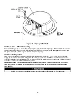
Figure 14
– Vent Terminal (Low Ground Clearance)
Summary of Contents for LUHE120T
Page 42: ...42 BMS Wiring Diagram...
Page 44: ...44 Lighting and Shutdown Instructions Figure 31 Lighting Instruction Label...
Page 62: ......
Page 63: ......


