background image

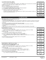
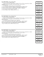
RETRIEVE STATUS REPORT (STATUS REQUEST)
PC must be connected directly to lock
Real time information for each lock, including:

  •  Solenoid status (activated or not)
  •  Mode (Setup or Operational)
  •  External Input (active or inactive)
  •  Bolt Switch Detection (N/A, Closed, Open, Opened and then Closed)
  •  Lock State (Normal, Time Delay, Open Window, Time Penalty)
  •  List can be exported in excel format

LOCK COnFIGURATIOn (REPORT REQUEST)
PC must be connected directly to lock
Set-up report for each lock, including:

  •  Lock Name
  •  Software version for the lock
  •  Time Delay (minutes 1-99)
  •  Open Window (minutes 1-19)
  •  Mode (Standard, Time Delay Override, Silent Alarm)
  •  Lock ID
  •  Lock State (Standard, Bolt Switch Detected, Set-up Ended, LED/button Interface Mode for use with open device, RTC Detected, 
    Memory Detected) 
  •  List can be exported in Excel format

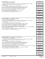
AUDIT DOWnLOAD (LOCK AUDIT REQUEST)
Can be retrieved either directly from lock or through the Logic Module
Each lock will record the last 4000 operations. The following information will be shown on the audit report:

  •  Number
  •  Date
  •  Time
  •  Last Name, First Name, Middle Initial
  •  Action

© copyright 2008  

(P/N)702.087 v1 • 8/08 

Kaba Mas LLC

page 6 of 11

2.0 MASTER MENU

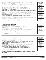
2.7.1 MASTER MEnU - Audit Functions - Audit Lock (Via Logic Module)
This function requires Logic Module Programming/Audit Cable (P/n 2041) and Total Audit software

1. Connect cable to PC and open Total Audit software on PC.  In the software window, select Audit Lock.
2. Select the appropriate COM port, lock ID and the number of events to be downloaded.
3. Place a check in the box marked, Via Logic Module.
4. Select a date range or leave circle for all events checked.
5. Connect cable to port on Logic Module.
6. Press any key to power up SMARTPOINT.
    •  Display will show either “ENTER CODE” or SELECT LOCK” when two or more locks are installed.
7. Hold down “zero” until the display shows “MASTER CODE, X-X-X-X-X-X-X-X”. Enter the Master code.
8. Press the P button four (4) times to select PC Link, the display will show “PC LINK”.
9. Press the OK button to start communication with the PC.
10. In the software window, select Get Data button.
    •  Once information has been sent, a new window will open showing the Audit Trail file.
11. Press the P to stop the communication.

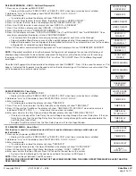
2.7.2 MASTER MEnU - Audit Functions - Logic Module Audit
This function requires Logic Module Programming/Audit Cable (P/n 2041) and Total Audit software

1. Connect cable to PC and open Total Audit software on PC.  In the software window, select Audit Controller.
2. Select the appropriate COM port and the number of events to be downloaded.
4. Select a date range or leave circle for all events checked.
5. Plug cable to port on logic module.
6. Press any key to power up SMARTPOINT.
    •  Display will show either “ENTER CODE” or SELECT LOCK” when two or more locks are installed.
7. Hold down “zero” until the display shows “MASTER CODE, X-X-X-X-X-X-X-X”.  Enter the Master code.
8. Press the P button four (4) times to select PC Link, the display will show “PC LINK”.
9. Press the OK button to start communication with the PC.
10. In the software window, select Get Data button.
  •  Once information has been sent, a new window will open showing the Audit Trail file.
11. Press the P to stop the communication.

MASTER CODE

XXXXXXXX

TIME/DATE

PC LINK

PC LINK

ENABLED

PC LINK

MASTER CODE

XXXXXXXX

TIME/DATE

PC LINK

PC LINK

ENABLED

Summary of Contents for SmartPoint

Page 1: ...ds page 3 2 3 Time Lock Special Events Verify page 3 2 3 1 Add Remove Special Events page 3 2 4 View Audit page 4 2 5 PC Link page 4 2 6 System Set up page 4 2 6 1 Install Locks to Logic Module page 4 2 6 2 Remove Locks from Logic Module page 5 2 6 3 Assign Lock page 5 2 6 4 System Operation Mode page 5 2 6 5 Access Limit page 5 2 6 6 System Information page 5 2 7 Audit Functions page 6 2 7 1 Audi...

Page 2: ...menu you can verify all stored opening periods 1 Press any key to power up SMARTPOINT Display will show either ENTER CODE or SELECT LOCK when two or more locks are installed 2 Hold down zero until the display shows MASTER CODE X X X X X X X X 3 Enter master code If a valid code is entered the display will show TIME DATE 4 Press P to select the next function the display will show TIME LOCK STAND WE...

Page 3: ...ER CODE X X X X X X X X 3 Enter master code If a valid code is entered the display will show TIME DATE 4 Press P two 2 times to select the next function the display will show TIME LOCK SPECIAL EVNT 5 Press OK to select Special Events Menus the display will show the first closing period stored 6 Press OK to scroll through all stored closing periods To delete an opening period first install a new op...

Page 4: ...tically based on number of days assigned System Information Shows firmware version set in Logic Module NOTE IF THERE IS A LOCK SET TO AUTO OPEN In a multiple lock system you can set an outer door lock to AUTO OPEN This will allow the user if authorized to open the inner compartment lock and have the outer door lock automatically open The AUTO OPEN lock always opens first SYSTEM SET UP 1 Press any ...

Page 5: ...tion options Options include USER CODE default 2 USER CODE FINGER ONLY FINGER CODE 2FINGERS 2FINGR 2CODE 5 After scrolling to appropriate operation press OK to select display will show SYSTEM OPER MODE 6 Press P to esc from menu 2 6 5 SYSTEM SET UP Access Limit Ability to disable users automatically based on number of days assigned if the Users code is not entered within the time frame assigned Fo...

Page 6: ... Logic Module 4 Select a date range or leave circle for all events checked 5 Connect cable to port on Logic Module 6 Press any key to power up SMARTPOINT Display will show either ENTER CODE or SELECT LOCK when two or more locks are installed 7 Hold down zero until the display shows MASTER CODE X X X X X X X X Enter the Master code 8 Press the P button four 4 times to select PC Link the display wil...

Page 7: ...n Unit will beep again and the display will show 2nd SCANNING then 3rd SCANNING Once scanning is completed the display will show ANOTHER FINGER The system offers the option of scanning up to three 3 fingers for each User or the Manager For optimal results finger should be lifted after each scan and then quickly replaced so that three separate captures are made Repeat this procedure for each finger...

Page 8: ...isplay will show TIME DATE 4 Press P six 6 times to select the User Menu the display will show USERS ON OFF 5 Press OK to view the User status the display will show USERS ON OFF XX XX 6 Press User ID XX to select a user display will show USER ID X DISABLE 7 Press OK display will show USERS ON OFF XX XX 2 8 4 MASTER MENU Users Enable A User 1 Press any key to power up SMARTPOINT Display will show e...

Page 9: ...P three 3 times display will show USER ID X ADD DEL MGR 8 Press OK display will show REMOVE MANAGER or MAKE MANAGER if the user was originally added without the manager feature added 9 Press OK display will show MANAGER REMOVED or MANAGER ADDED 10 Press OK display will show USERS ON OFF XX XX 2 8 7 MASTER MENU Users Add Remove Time Delay Override 1 Press any key to power up SMARTPOINT Display will...

Page 10: ...r up SMARTPOINT Display will show either ENTER CODE or SELECT LOCK when two or more locks are installed 2 Hold down zero until the display shows MASTER CODE X X X X X X X X 3 Enter master code If a valid code is entered the display will show TIME DATE 4 Press P seven 7 times to select the TIme Delay Menu the display will show TIME DELAY 5 Press OK to enter the Time Menu the display will show TIME ...

Page 11: ... ENTER MASTER MENU 31 ENTER MANAGER MENU 32 ENTER TIME MENU 33 ENTER PC LINK 34 LEAVE PC LINK 40 SET TIME DATE 41 SET TIME LOCK 42 SET SPECIAL EVENT 43 LOCK INSTALL 44 LOCK REMOVE 45 MANAGER INSTALL 46 MANAGER DELETE 47 ASSIGN LOCK 48 VIEW AUDIT 4A MANAGER FINGERPRINT ENROLL 4B SET SYSTEM OPERATION MODE 4C SET IMMEDIATE TIME LOCK 4D SET OPEN OFFSET 4E SET EXTENSION TIME 4F SET ACCESS LIMIT 50 RTC ...

Reviews: