La Crosse Technology TX2000 Discovery Manual Download Page 19


19

4)


Remove the protective strip from the other side of the 
tape. 

5)


Position the remote temperature sensor in the desired 
location, ensuring that the indoor weather station can 
receive the signal. 


II.  THE INDOOR THERMO STATION


The indoor thermo station can be mounted in two ways: 

• 

with the table stand or, 

• 

on the wall with the use of a wall hanging screw (not 
included). 


A.  USING THE TABLE STAND


The indoor thermo station comes with the table stand 
already mounted.  If you wish to use the table-stand all 
that is required is to place the indoor weather station in 
an appropriate location. 
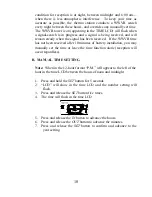
 

B.  WALL MOUNTING


1) Remove the table-stand.  To do this, pull down on the 

stand from the rear and rotate forward. 

2) Fix a screw (not included) into the desired wall, 

leaving approximately 3/16 of an inch (5mm) 
extended from the wall. 

3) Place the indoor thermo station onto the screw using 

the hanging hole on the backside. 

4) Gently pull the indoor thermo station down to lock the 

screw into place.   


TROUBLESHOOTING 


NOTE: For problems not solved, please contact La Crosse Technology. 


Problem: 

No reception of WWVB time signal. 

Solution: 

1) Wait overnight for signal. 

2) Be sure indoor thermo station is at least 6 feet from any electrical devices, such 

as televisions, computers, or other radio-controlled clocks. 

3) Remove batteries for five minutes, reinsert and leave the unit alone overnight 

without pressing buttons. 

4) If there are still problems, contact La Crosse Technology 

Summary of Contents for TX2000 Discovery

Page 1: ...ime Setting 12 24 Hour Time Setting Time Setting WWVB Manual Setting the Year Day and Month Setting the Snooze Setting the Temperature Format Features Indoor Temperature Outdoor Temperature Minimum Ma...

Page 2: ...s at 60 kHz The signal can be received up to 2 000 miles away through the internal antenna in the Weather Station However due to the nature of the Earth s Ionosphere reception is very limited during d...

Page 3: ...aded area The remote temperature sensor has a range of 330 feet Any walls that the signal will have to pass through will reduce distance An outdoor wall or window can have up to 30 feet of resistance...

Page 4: ...n push up and pull out on the battery cover 2 Observe the correct polarity and install 2 AA batteries 3 Replace the battery cover Note Immediately after the batteries have been installed the LCD Liqui...

Page 5: ...he program mode during the programming of sections III through XI you can advance to step 4 of the next program setting If you do leave the program setting or want to program a specific setting follow...

Page 6: ...ut and down III SETTING THE LCD CONTRAST 1 Press and hold the SET button for 5 seconds 2 LCD will show in the time LCD and the number setting will flash Note There are 8 LCD contrast levels to choose...

Page 7: ...lect your time zone Note When a time zone for the U S is selected the corresponding abbreviation will appear above the time please see the table It is possible to select any time zone from 12 GMT to 1...

Page 8: ...he feature is on and the WWVB will change times automatically Note Some locations Arizona and parts of Indiana do not follow Daylight Saving Time and should select DST 0 6 Press and release the SET bu...

Page 9: ...24 hour time format Note When in the 12 hour format P M will appear to the left of the hour in the time LCD between the hours of noon and midnight 6 Press and release the SET button to confirm and adv...

Page 10: ...eived after 10 minutes of battery installation you may manually set the time or leave the time function alone reception will occur regardless B MANUAL TIME SETTING Note When in the 12 hour format P M...

Page 11: ...and release the IN button to advance the year 6 Press and release the SET button to confirm and advance to the day month setting 7 The day and month will flash in the date LCD 8 Press and release the...

Page 12: ...15 20 25 or 30 minutes XI SELECTING F OR C 1 Press and hold the SET button for 5 seconds 2 LCD will show in the time LCD and the number setting will flash 3 Press and release the SET button nine time...

Page 13: ...the OUTDOOR LCD This feature is explained in further detail in section V Adding Remote Temperature Sensors III MINIMUM AND MAXIMUM TEMPERATURE RECORDS The TX2000 keeps a record of the MINIMUM and MAX...

Page 14: ...NG THE OUTDOOR TEMPERATURE RECORDS 1 Press the OUT button once MIN appears above the outdoor temperature and the LCD will flash indicating that the minimum temperature and the time and date of occurre...

Page 15: ...OUT button to set the alarm minutes 3 Press the AL1 button or wait 15 seconds for the unit to automatically confirm the alarm time and return to display the date in the DATE LCD as normal 4 The 1 icon...

Page 16: ...ifferent remote temperature sensors The remote temperature sensor model s that you choose will come with their own set of instructions follow these instructions for a complete guide to setting up Foll...

Page 17: ...tton A shift from one boxed number to the next should be observed in the OUTDOOR LCD 2 To view the Minimum Maximum temperature first select which remote temperature sensor to read data from indicated...

Page 18: ...o ensure that there is proper reception The thermo station should display a temperature in the OUTDOOR LCD within 4 minutes of setting up I THE REMOTE TEMPERATURE SENSOR The remote temperature sensor...

Page 19: ...tand To do this pull down on the stand from the rear and rotate forward 2 Fix a screw not included into the desired wall leaving approximately 3 16 of an inch 5mm extended from the wall 3 Place the in...

Page 20: ...ecause the sensors are designed for different working environments The indoor sensor is less responsive to ambient air currents because of the shielding effect of the display s case In addition the ca...

Page 21: ...in 190 x 75 x 27 5mm Remote temperature 5 03 x 1 57 x 0 86 in 128 x 40 x 22 mm WARRANTY INFORMATION La Crosse Technology Ltd provides a 1 year limited warranty on this product against manufacturing de...

Page 22: ...amage resulting from failure to follow instructions contained in your owner s manual 5 damage resulting from the performance of repairs or alterations by someone other than an authorized La Crosse Tec...

Page 23: ...ntain mistakes and printing errors The information in this handbook is regularly checked and corrections made in the next issue We accept no liability for technical mistakes or printing errors or thei...

Reviews: