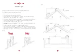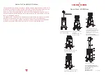
ASSEMBLY SCHEMES
ASSEMBLY SCHEMES
Round Stack - SLIM, RIM,
LONG and SIDE base
Rondò
Chimney flue hole
1. Position the fireplace
in axis with the flue pipe
hole.
4. Insert ceramic fireplace
from above. Put it near the
door.
6. Stack ceramic top cover.
Connect to the chiminey
flue.
5. Insert the following cera-
mic rings from above.
Ashes cleaning from the
door with a proper shovel.
3. Brass door assembly
with 4 M6 screws in the four
corners under the gasket.
Put 2 M4 screws in the
middle of the door.
2. Insert ceramic base
from above.
Insert primary air dipstick
in its hole and screw it.
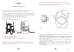
Chimley flue hole
1. Position the fireplace in axis
with the flue pipe hole.
2. Unscrew and remove
exchanger.
Put the 1st ceramic ring
on the wood base.
3. Door flange assembly with
screws M6. To screw the flange,
slightly move the 2 lateral
refractory bricks. Start screwing
n¡1 and n¡2.
When finished (all screws)
stack the exchanger and screw it.
4. Stack fom above
the second fireplace ceramic ring.
Tuck the door into its hinges.
5. Stack the third ceramic pierced
body element and the top cover.
6. Flue pipe connection
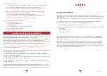
1= First fireplace ceramic ring
2= Second fireplace ceramic ring
3= Third ceramic ring
4= Top cover
5= Ceramic column
6= Ceramic Cube
°
°
3-12 of 3-14
Summary of Contents for Stack
Page 2: ......
Page 10: ...1 7 of 1 41 ...
Page 15: ...1 12 of 1 41 ...
Page 16: ...1 13 of 1 41 ...
Page 17: ...1 14 of 1 41 ...
Page 18: ...di R Perino e S Neri S n c 1 15 of 1 41 ...
Page 19: ...di R Perino e S Neri S n c 1 16 of 1 41 ...
Page 20: ...di R Perino e S Neri S n c 1 17 of 1 41 ...
Page 21: ...di R Perino e S Neri S n c 1 18 of 1 41 ...
Page 22: ...di R Perino e S Neri S n c 1 19 of 1 41 ...
Page 23: ...di R Perino e S Neri S n c 1 20 of 1 41 ...
Page 24: ...di R Perino e S Neri S n c All holes Ø 6mm 1 21 of 1 41 ...
Page 25: ...1 22 of 1 41 ...
Page 26: ...1 23 of 1 41 ...
Page 27: ...1 24 of 1 41 ...
Page 28: ...1 25 of 1 41 ...
Page 29: ...1 26 of 1 41 ...
Page 30: ...1 27 of 1 41 ...
Page 31: ...1 28 of 1 41 ...
Page 32: ...1 29 of 1 41 ...
Page 33: ...1 30 of 1 41 ...
Page 34: ...1 31 of 1 41 ...
Page 35: ...1 32 of 1 41 ...
Page 36: ...1 33 of 1 41 ...
Page 37: ...1 34 of 1 41 ...
Page 48: ...2 4 of 2 57 ...
Page 49: ...2 5 of 2 57 ...
Page 50: ...2 6 of 2 57 ...
Page 51: ...2 7 of 2 57 ...
Page 52: ...2 8 of 2 57 ...
Page 53: ...2 9 of 2 57 ...
Page 54: ...2 10 of 2 57 ...
Page 55: ...2 11 of 2 57 ...
Page 56: ...2 12 of 2 57 ...
Page 57: ...2 13 of 2 57 ...
Page 58: ...2 14 of 2 57 ...
Page 59: ...2 15 of 2 57 ...
Page 60: ...2 16 of 2 57 ...
Page 61: ...2 17 of 2 57 ...
Page 62: ...2 18 of 2 57 ...
Page 63: ...2 19 of 2 57 ...
Page 64: ...2 20 of 2 57 ...
Page 65: ...2 21 of 2 57 ...
Page 66: ...2 22 of 2 57 ...
Page 68: ...2 24 of 2 57 ...
Page 69: ...2 25 of 2 57 ...
Page 70: ...2 26 of 2 57 ...
Page 71: ...2 27 of 2 57 ...
Page 72: ...2 28 of 2 57 ...
Page 73: ...2 29 of 2 57 ...
Page 74: ...2 30 of 2 57 ...
Page 75: ...2 31 of 2 57 ...
Page 76: ...2 32 of 2 57 ...
Page 77: ...2 33 of 2 57 ...
Page 78: ...2 34 of 2 57 ...
Page 79: ...2 35 of 2 57 ...
Page 80: ...2 36 of 2 57 ...
Page 81: ...2 37 of 2 57 ...
Page 82: ...2 38 of 2 57 ...
Page 83: ...2 39 of 2 57 ...
Page 84: ...2 40 of 2 57 ...
Page 85: ...2 41 of 2 57 ...
Page 86: ...2 42 of 2 57 ...
Page 87: ...2 43 of 2 57 ...
Page 88: ...2 44 of 2 57 ...
Page 89: ...2 45 of 2 57 ...
Page 90: ...2 46 of 2 57 ...
Page 91: ...2 47 of 2 57 ...
Page 103: ...INSTRUCTION MANUAL FOR INSTALLATION USE AND MAINTENANCE TYPE RNO 200 MODEL 3 2 of 3 14 ...
Page 121: ...4 6 of 4 40 ...
Page 122: ...4 7 of 4 40 ...
Page 123: ...4 8 of 4 40 ...
Page 128: ...4 13 of 4 40 ...
Page 129: ...4 14 of 4 40 ...
Page 130: ...4 15 of 4 40 ...
Page 133: ...4 18 of 4 40 ...
Page 134: ...4 19 of 4 40 ...
Page 138: ...4 23 of 4 40 ...
Page 139: ...4 24 of 4 40 ...
Page 140: ...4 25 of 4 40 ...
Page 145: ...4 30 of 4 40 ...
Page 146: ...4 31 of 4 40 ...
Page 147: ...4 32 of 4 40 ...
Page 152: ...4 37 of 4 40 ...
Page 153: ...4 38 of 4 40 ...
Page 154: ...4 39 of 4 40 ...


