background image


3-2 

HP01-TS software


3.3 Installing HP01-TS 
     Software 


Before connecting the Magnetic field analyzer to PC the HP01-TS software 
installation should be performed: 
 
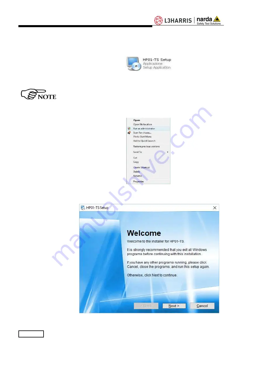
Double click on the file “HP01-TS  Setup.exe” included on Software Media 


Fig. 3-1 

Setup icon 


The  User  must  have  administrator  privileges  to  install  the  HP01-TS 
software in Windows Vista, Windows 7, Windows 8.1 and Windows 10; 
right click on the program .exe file and click on “Run as administrator” 
to temporarily run the program or application as an administrator until 
close  it  (Windows  7  also  allows  to  mark  an  application  so  that  it 
always runs with administrator rights). 


Fig. 3-2 

Run as administrator 

 
Follow set-up program instructions  


Fig.3-3

 HP01-TS installation 

Summary of Contents for HP-01

Page 1: ...rial Number on the upper side panel of the instrument The Serial Number is in the form 000XY00000 The first three digits and the two letters are the Serial Number prefix the last five digits are the Serial Number suffix The prefix is the same for identical instruments it changes only when a configuration change is made to the instrument The suffix is different for each instrument Document HP01EN 1...

Page 2: ...ETY SYMBOLS You now own a high quality instrument that will give you many years of reliable service Nevertheless even this product will eventually become obsolete When that time comes please remember that electronic equipment must be disposed of in accordance with local regulations This product conforms to the WEEE Directive of the European Union 2002 96 EC and belongs to Category 9 Monitoring and...

Page 3: ...6 Power supply and battery recharging 2 7 HP 01 connected to a PC 2 8 HP 01 with 8053B 2 9 Battery management 2 10 Avoiding measurement errors 2 1 2 1 2 1 2 1 2 1 2 2 2 3 2 3 2 3 2 4 3 EHP TS installation Page 3 1 Introduction 3 2 Hardware requirements 3 3 Installing HP TS Software 3 1 3 1 3 2 4 HP TS software Page 4 1 HP TS Applications 4 2 HP01 TS Application 4 2 1 Main menu 4 2 2 TOT and XYZ mo...

Page 4: ...ssories Page 8 1 Introduction 8 1 1 Preliminary inspection 8 1 2 Work environment 8 1 3 Return for repair 8 1 4 Cleaning 8 1 5 Power supply and battery chargers 8 2 USB OC Optical USB Converter 8 2 1 Introduction 8 2 2 Installation 8 1 8 1 8 1 8 1 8 1 8 2 8 3 8 3 8 3 9 Communication protocol Page 9 1 Disclaimer 9 2 Protocol 9 3 Leds behaviour 9 4 HP 01 COMMANDs 9 4 1 Query Commands 9 4 2 Setting C...

Page 5: ...play Minimized UI Info toolbar Zero Gauss Chamber Zeroing Successful zeroing Span selector Averaging Plot graph Scale selector Settings and Save buttons Save file Plot Total Settings Spectrum graph Span selection Waterfall screen OpenGL version warning Waterfall 2D Graph 2D Marker Export tool Waterfall 3D Graph Update software icons HP 01 Upgrading utility main window Switch HP 01 on Update firmwa...

Page 6: ... remove confirmation request Uninstallation successful Control panel Application installation Uninstalling USB OC Uninstaller messages USB OC adapter 6 1 6 1 6 2 6 2 7 1 7 1 7 2 7 2 8 3 Tables Table Page 1 1 8 1 Technical Specifications of the HP 01 USB OC Technical Specifications 1 4 8 3 ...

Page 7: ...terruption or loosening of the ground wire or of a connecting power cable inside or outside the device will cause a potential risk for the safety of the personnel Ground connections must not be interrupted To prevent the possible danger of electrocution do not remove any covers panels or guards installed on the device and refer only to NARDA Service Centers if maintenance should be necessary To ma...

Page 8: ...ly sulla base delle seguenti norme europee armonizzate applicate con esito positivo based on the following harmonized European Standards successfully applied EMC Emissioni EMC Emission EN 61326 1 2013 EMC Immunità EMC Immunity EN 61326 1 2013 Sicurezza Safety EN 61010 1 2010 dichiara sotto la propria responsabilità che il prodotto declares under its sole responsibility that the product Descrizione...

Page 9: ...uency and level calibration tables and an internal optical repeater which allows connection to external devices through the optical fibre Spectral analysis obtained through DSP Digital Signal Processor is performed on different frequency Span values and displayed on the PC monitor Marker function is available to provide accurate field strength and frequency measurement HP 01 is managed internally ...

Page 10: ...1 2 General Information The notch near the end of the tip marks the sensor position The orientation of the three axis is depicted onto the top panel Fig 1 1 Sensor position ...

Page 11: ...OM including User s Manual Cerfiticate of Calibration The HP 01 Set for 8053B and PC use includes the following items available for Italy only HP 01 Basic Unit Zero Gauss Chamber AC DC Converter with Italian plug adapters Cable FO Duplex RP 02 10m USB OC Optical Converter Cable FO Duplex HFBR 10m Conical Tripod support Carrying Case 170 37 HP TS Software Media including User s Manual Cerfiticate o...

Page 12: ...cy User selectable within the whole range Time domain analysis method DC to 1 Hz FIR filter 1 Hz 3dB reading updating time 67 ms Calibration 6 internal E2PROM Temperature and humidity meter 20 to 55 C 0 01 resolution 5 to 95 0 1 resolution Typical temperature deviation 0 Hz referred to 23 C 0 05 C Dimensions Sensor stick φ 9 mm L 143 mm Main body φ 43 mm L 55 mm Overall length 200 mm Weight 100 g ...

Page 13: ...General Information 1 5 1 6 HP 01 Panel Key 1 Power on LED 2 Battery charger connector 3 ON OFF button 4 Fiber optic connector 5 Data LED Fig 1 2 Panel of HP 01 ...

Page 14: ...1 6 General Information This page has been intentionally left blank ...

Page 15: ...air please complete the questionnaire appended to this User s Manual filling in all the data that will be useful for the service you have requested For reducing the period of time required for the repairs it is necessary to be as specific as possible in describing the problem If the problem only occurs in certain circumstances please describe in detail how it happens If possible it is better to re...

Page 16: ...t is crucial to have a complete recharge before storing them for periods longer than 4 months Therefore it is warmly suggested recharging the batteries at least every 4 months even though the device has not been used The minimum voltage level for operation is about 3 25V The batteries must be recharged for lower voltages Below such voltage the analyzer will turn OFF automatically The time required...

Page 17: ...ftware 2 8 HP 01 with 8053B HP 01 is linked to 8053B via the fiber optic link Switch the unit on with a short key press of the Power button wait 2 seconds and press the key a second time until the ON LED lights up to set the probe for communication with 8053B Please see 8053B Manual for further details 2 9 Battery management The battery autonomy of the Analyzer depends on its mode of operation It ...

Page 18: ...ence the measurements and therefore determine incorrect results We recommend always using the amagnetic extension support supplied with HP 01 for supporting the Analyzer The intensity of the measured field mainly depends on its currents and the geometry of the system under examination as well as the distance between the conductors magnets and the measurement points In the vicinity of cables the re...

Page 19: ...onnected to PC in order to run The HP01 TS installation program automatically installs the driver for USB optical converter 3 2 Hardware requirements Minimum requirements Processor Pentium or equivalent 256 MB RAM At least 64 MB of free space on hard disk 1 free USB port Windows Operating system XP Vista Win7 Win8 1 Win10 The User might have the need of administrator privileges to install the soft...

Page 20: ...must have administrator privileges to install the HP01 TS software in Windows Vista Windows 7 Windows 8 1 and Windows 10 right click on the program exe file and click on Run as administrator to temporarily run the program or application as an administrator until close it Windows 7 also allows to mark an application so that it always runs with administrator rights Fig 3 2 Run as administrator Follo...

Page 21: ...HP01 TS software 3 3 Fig 3 4 Installation folder Fig 3 5 Ready to install ...

Page 22: ...01 TS Fig 3 7 Installation successful When asked for reboot your system to complete installation Fig 3 8 Reboot HP01 TS software is now installed in your PC you can remove it if needed simply running the Uninstall HP01 TS application see cap 8 ...

Page 23: ... 01 analyzer is connected to PC HP01UP this is the tool for internal firmware upgrading Uninstall HP01 TS this is a tool to remove the software package from the PC This document describes applications for HP 01 analyzer only The User might have the need of administrator privileges to install the software in Windows Vista 7 8 1 and 10 for further information see the paragraphs in Chapter 3 If the b...

Page 24: ...spectrum analysis included in HP TS software package Connect HP 01 to the USB port of your PC using provided optical fibre and USB OC optical to USB converter Switch the analyzer ON and run HP TS application a welcome screenshot will appear for a few seconds Fig 4 2 Welcome logo Then the program HP01 TS main window will be shown Fig 4 3 HP01 TS Main Window ...

Page 25: ...2 Exit button to terminate application 13 Blinking green square shows valid connection blinking red square means connection in progress static gray square means connection to the probe managed by another window e g Spectrum graph 14 Display of parameters see below 15 Stop or Run button to momentary suspend the samples acquisition Press again to resume 16 Zero button to run the zeroing procedure in...

Page 26: ...unit can be mT G or T kG depending on the level range and unit setting Fig 4 4 Total and XYZ display 4 2 3 Minimized UI A minimized visualization is also available and it can be activated under the Preference menu If active a small window with the Total Field value is shown on the screen when trying to reduce the main window to icon Fig 4 5 Minimized UI ...

Page 27: ...inate the Earth magnetic field then click on the Zero button Fig 4 7 Zero Gauss Chamber Then click Yes and please wait for the zeroing process to complete Fig 4 8 Zeroing Fig 4 9 Successful zeroing At the end of the zeroing procedure please remove the Zero Gauss Chamber The analyzer is immediately ready to be used Please pay attention the Zero Gauss Chamber is a very fragile tool It must be handle...

Page 28: ...th RBW selectivity of the measurements is depending on the Span setting Span RBW 20 Hz 30 Hz 100 Hz 1000 Hz 0 8 Hz 1 2 Hz 4 Hz 10 Hz 4 2 7 Average This function can be used to select the proper averaging for the displayed level The number between 1 OFF and 64 corresponds to the quantity of measurements participating in the calculation of the mean value Fig 4 11 Averaging ...

Page 29: ...nd Fstop depending on the selected Span We recommend to consider the following settings for best results To obtain accurate integration results the minimum setting for Fstart should be Fstart 2 x RBW To obtain accurate integration results the minimum bandwidth Fstop Fstart should be Fstop Fstart 4 x RBW The values for RBW are given above in chapter 4 2 6 Span ...

Page 30: ...d T Total traces It will show the time and the level measured for that time The vertical axis shows the level which can be chosen among several full scales The horizontal axis shows the time course of the field in seconds starting from the right to the left with the latest measurement on the right The time scale can be set under Settings from 1 s to 1000 s per division Hold or Run Pauses or resume...

Page 31: ...ements can be saved in a text file using this function To enable the Settings and Save buttons it is necessary to stop acquisition by clicking the Hold button Fig 4 14 Settings and SaveButtons Fig 4 15 Save file This section allows to input the name of the file which will contain all the measurements acquired up to the time the Hold button was clicked ...

Page 32: ... the appearance of the program Fig 4 17 Settings Display Plot Plot Spectrum Spectrogram Waterfall boxes allow selecting each environment parameters and color palette Default button to set appearance to the default parameters Press Save button to store the specific choice ...

Page 33: ...minimum operating frequency is DC and maximum stop frequency is about equal to the span itself The resolution bandwidth depends on the selected span HP 01 performs selective measurement over the entire frequency range defined by the Span setting HP TS is able to select data in order to display a user specified marker frequency within the selected span For this purpose the Marker function can be ac...

Page 34: ...s displayed The desired Span can be selected among four choices available as depicted below Fig 4 19 Span selection Spectrogram and Waterfall the buttons S and W allow the User to select the waterfall display It can be the Spectrogram 2D view or the Waterfall 3D view The Waterfall graph is used to explore the trend over time of the signals in the frequency domain ...

Page 35: ...ectrogram plot and a tridimensional Waterfall graph The two dimensions are frequency and time and the third dimension is the level Level variations can also be distinguished by differences in color In this way it is possibile to detect and track time varying signals The ranges for Frequency and Level are the same as the Spectrum view When entering the Waterfall function a screen similar to the fol...

Page 36: ...y The Color Scale referenced to levels and units is indicated on the left bar on the screen Fig 4 22 Waterfall 2D Graph A Marker function is also available to allow investigating a specific signal Fig 4 23 2D Marker In the box indicated by the arrow it is shown the Frequency of the Marker 5 00 Hz in the example above the level 0 226 mT and the time of the trace since the waterfall window was start...

Page 37: ... the marker can be placed by a left click of the mouse over any point of the signals while the graph aspect can be changed as desired by clicking the right button and dragging the mouse in a simple and intuitive way Use the mouse wheel for zooming By choosing the appropriate functions pointing the most suitable area the User can move rotate and zoom the view to his liking simply using the mouse Fi...

Page 38: ...4 16 Description This page has been intentionally left blank ...

Page 39: ...n 5 2 To run the update software Turn off the HP 01 and connect it to a free USB port of the PC Run HP 01 Update Firmware to start the update program Fig 5 1 HP 01 Update software icons 5 3 To transfer data Main window displayed after the updating program HP 01 Update Firmware has been run Fig 5 2 HP 01 Upgrading utility main window Select USB or RS232 communication port Before selecting RS232 por...

Page 40: ...ss OK to confirm The following window will appear Fig 5 4 Update firmware The firmware components can be updated by this application The Firmware is the main analyzer internal program and it is automatically stored within the HP01 TS directory during HP01 TS software installation To start the process simply select Update Firmware button and wait less than one minute until the automatic transfer is...

Page 41: ... 01 OFF it could seem to be already OFF but it is not and turn it ON again The HP 01 is now updated with the new version of the internal firmware It is now possible to disconnect the cable connected to the PC with the HP 01 meter either switched on or off Subsequently when the meter is switched on again the new version will be displayed in the 8053B or HP01 TS application software To obtain firmwa...

Page 42: ...5 4 Firmware Update This page has been intentionally left blank ...

Page 43: ...HP TS Software It is possible to remove the HP TS software from the PC according to the following procedure Run the Uninstall HP01 TS utility Fig 6 1 Uninstall icon Follow the uninstaller instructions Fig 6 2 Uninstalling HP01 TS 1 Document HP01EN 10707 1 05 NARDA 2021 ...

Page 44: ...ask for a confirmation Answer NO in case you are not sure whether the showed system file is required for other applications Fig 6 3 File remove confirmation request Fig 6 4 Uninstallation successful HP01 TS software is now removed from the system click Finish to close uninstaller utility ...

Page 45: ... PC according to the following procedure The following procedure shows how to remove the driver in Windows XP environment It may be different depending on the operating system in use Open the Windows Control Panel Fig 7 1 Control panel Double click Add or Remove Programs Fig 7 2 Uninstall icon 1 Document HP01EN 10707 1 05 NARDA 2021 ...

Page 46: ...select FTDI FTD2XX USB Drivers and click Change Remove Fig 7 3 Uninstalling USB OC Unplug the USB OC converter if connected and click Continue Fig 7 4 Uninstaller messages Click finish to exit the uninstaller USB driver is now removed from your system ...

Page 47: ...llowing conditions Temperature Humidity From 30 C to 70 C 20 C to 60 C for Battery Charger 95 relative 8 1 3 Return for repair When the Accessories need to be returned to NARDA for repair please complete the questionnaire appended to this User s Manual filling in all the data that will be useful for the service you have requested For reducing the period of time required for the repairs it is neces...

Page 48: ...accessories The battery charger has an internal protective circuit that will break the output if any load is detected while connecting to the mains Battery charger output DC 10 15 V 500 mA Connector In order to preserve battery efficiency a complete recharge cycle is required before storing them for periods longer than 4 months Therefore it is warmly suggested recharging the batteries at least eve...

Page 49: ...ed items via a Personal Computer and the related update software is available free of charge on NARDA s Web site at http narda sts it 8 2 2 Installation Insert USB OC in the connector of a free USB port of the PC connect the fiber optic coming from the probe or other Accessories treating the locating key with care Considering the very low consumption of the device the power required by USB OC is t...

Page 50: ...8 4 Accessories This page has been intentionally left blank ...

Page 51: ... ASCII string delimited by 0x23 and 0x2A Every command must start with the header H1 The answer can be either in ASCII or Binary according to the command sent The HP 01 must be switched on in PC mode in order the communication protocol to work properly This is the same standard mode used with the provided software If the Magnetometer will continue sending measurement data independently by receivin...

Page 52: ...sful communication then DATA LED switches to red DATA LED is off when HP 01 is being charged Power on LED Power on LED blinks roughly with 0 5s period only when HP 01 is powered When HP 01 is still on charge Power on LED is orange whereas when HP 01 has finished charging still powered Power on LED is green Power on LED blinks red when the User tries to switch off HP 01 when powered not allowed act...

Page 53: ...d field HP 01 replies with the received command followed by ERROR string Example H1 SIPA Reply SIPA ERROR Query COMMANDs Syntax Function H1 BAT Battery voltage H1 DCE Filter output 3dB 1Hz H1 FLD f 3 axis field value at f Hz Verbose H1 FLP a fs fe Wide band field channel power over fs fe Hz span on axis a H1 FLS a f Field value at f Hz on axis a H1 FLW a fs fe Wide band field over fs fe Hz span on...

Page 54: ...s occurred Example H1 DCE Reply DCE 0 0640 S X 0 0581 S Y 0 2200 S Z 0 23 64 T mT 17 Example H1 DCE Reply DCE 86 8121 N X 86 9110 N Y 50 1291 S Z 132 6755 T mT 12 Example H1 DCE Reply DCE 0 0508 S X 0 0813 S Y 0 2257 S Z 0 24 53 T T 24 FLD f Verbose field query command The command must specify the frequency f at which the field has to be evaluated The reply is in the format FLD fHz u x a y b z c t...

Page 55: ...fe a where vx is the wide band field on the x axis similar for y and z axis vt is the total wide band field u is the measurement unit fs is the start frequency in Hz fe is the end frequency in Hz a is axis which can be X Y Z or T An error is returned when fe is lower than fs 10 frequency resolution or when fe is higher than the span Frequency values may differ from the requested ones because they ...

Page 56: ...een measured a is axis which can be X Y Z T Or in the format FLS vx X vy Y vz Z vt T u f where vx is the field on the x axis similar for y and z axis vt is the total field u is the measurement unit f is the frequency in Hz at which the field has been measured this value may differ from the requested one because it depends on the selected frequency resolution span setting An error is returned when ...

Page 57: ...s the total wide band field u is the measurement unit fs is the start frequency in Hz fe is the end frequency in Hz a is axis which can be X Y Z or T An error is returned when fe is lower than fs 10 frequency resolution or when fe is higher than the span Frequency values may differ from the requested ones because they depend on the selected frequency resolution span setting means an over range has...

Page 58: ... axis similar for y and z axis u is the measurement unit f is the filter frequency in Hz related to the selected span means an over range has occurred Example H1 GDCX Reply GDC 0 10 mT 0 5 0 X N Example H1 GDCT Reply GDC 0 79 T mT 0 5 0 Example H1 GDC Reply GDC 0 09 N X 0 78 S Y 0 09 N Z 0 00 T mT 0 5 0 IDN Identifier query The answer displays the name of the machine its serial number the firmware...

Page 59: ... is in the format RDY x where Y new spectrum and data are both available N no spectrum and no data are available since last SPC FLD FLW FLS or GDC queries Example H1 RDY Reply RDY Y RNG Sensor range query command The reply is in the format RNG x Where x reports on the span A Automatic range H High range L Low range Example H1 RNG Reply RNG L SPA Span mode query command The reply is in the format S...

Page 60: ...mand The command must be in the format RNG x The reply is in the format RNG x where x is an index to indicate the span A Automatic range H High range L Low range In automatic mode sensor range is selected automatically to optimize the sensitivity and avoid saturation phenomena When High or Low mode are selected respectively high and low sensor range is enforced Example H1SRNG Reply RNG L SZESI Ini...

Page 61: ...matic DCE values 15 measurements per second Reply formatted as described for H1 DCE command DCE mode makes unavailable commands such as SPA GDC FLS etc In case of one of these commands the reply would be DCE ERROR Example H1SDCE 0 Reply DCE 0 Example H1SDCE 1 Reply DCE 1 Example H1SDCE 2 Reply DCE 2 DCE 0 0698 N X 0 0602 S Y 0 3048 S Z 0 3 185 T mT 21 DCE 0 0704 N X 0 0598 S Y 0 3050 S Z 0 3 187 T...

Page 62: ...nted parameters and then ask for the spectrum and read the reply Spectrum Structure Header Bytes Position Mnemonic Type Description 2 0 bytes2beSent Uint Total number of bytes 2 2 Reserved Uint 2 4 Bat Uint Battery 2 6 SpanId Uint Id of Span 2 8 Range Uint Id of Range 2 10 Bins Uint Used Bins frequencies 2 12 overrange Uint 0 no overflow 0 overflow 2 14 Reserved Uint 4 16 scaleFact X float Factor ...

Page 63: ...ns Last Bin Lev Uint Spectrum Y 2 2 32 2 Bins 1st bin lev Uint Level to be multiplied by scaleFact Y 2 4 32 2 Bins 2nd bin lev Uint 2 Uint 2 32 4 Bins Last Bin Lev Uint Spectrum Z 2 2 32 4 Bins 1st bin lev Uint Level to be multiplied by scaleFact Z 2 4 32 2 Bins 2nd bin lev Uint 2 Uint 2 32 6 Bins Last Bin Lev Uint 2 2 32 6 Bins Reserved Uint Terminator 2 4 32 6 Bins dual char ...

Page 64: ...9 14 Communication protocol This page has been intentionally left blank ...

Page 65: ...u would like to submit to the attention of our service organization is kept in great consideration Moreover we are continuously improving our quality but we know this is a never ending process We would be glad if our present efforts are pleasing you Should one of your pieces of NARDA equipment need servicing you can help us serve you more effectively filling out this card and enclosing it with the...

Page 66: ...Suggerimenti Commenti Note Suggestions Comments Note ...

Reviews: