MPM-1000A Operator Manual
1000-7075 Rev D
6-3
Table 6-1 Configure System Configuration Screen
Control/Indicator/Function
Description
Manual GPS Entry
Enables input of the Terminal geographic location. The Modem uses this
information to calculate various Satellite link parameters when in the NCW
mode of operation.
GPS
Current values of the attached GPS (if any).
Internal Modem Temperature
Current
Displays the current Modem temperature value.
High Thresh
High threshold to create an alarm.
Low Thresh
Low threshold to create an alarm.
Block Converter
Captures input of external block converter parameters, which must be
entered when configuring an MPM-1000A. The Modem software uses the
block converter frequencies and the satellite uplink and downlink
frequencies to compute and set the Modem transmit and receive
frequencies.
Antenna
Allows you to select antenna type. Two antenna types are available:
Circular Aperture and FSS-4180-LP. If Circular Aperture type is selected,
then Aperture size in inch/meters is available to you. You can use the
up/down arrows to set the antenna aperture.
Rx Attenuator
RF Noise Temperature
Antenna Noise Temperature. (See Section 16)
Rx Gain
Terminal Receiver Gain. (See Section 16)
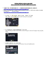
6.2 Configure Modem Screen
The
Bandwidth Segment I/F Range
items show the NCW operating frequencies. If
either TX or RX is out of range, the HCI will not allow you to initiate or join a network.
(See Figure 6-3)
Refer to Table 6-2 Modem Screen for data descriptions for this window.
Figure 6-3 Modem Screen


