background image


19 

Heating/Ventilating/Cooling Operating 
Modes


The  AireLogic  DDC  controller  automatically  switches  between  the  heating,  ventilating 
and  cooling  modes  of  operation.  The  previous  sections  described  the  Heating  and 
Cooling  Setback  operation.  This  section  concentrates  primarily  on  the  Occupied 
operating  modes.  Figures  1  and  2  provide  a  pictorial  representation  of  the  slight 
differences between the occupied and unoccupied periods. 

Heating Mode 

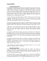
Depending on the control type, the Occupied Heating Mode allows the burner to operate 
as needed and is activated whenever the room or outside air temperature is 2°F below the 
heating setpoint. During the Unoccupied Heating Mode, the burner is activated whenever 
the room or outside air temperature is at the heating setpoint and is deactivated 2°F above 
the heating setpoint. 
 

MDT and MDT-Expert control systems do not require a room sensor. As such, one 
is  not  provided  for  units  that  ship  from  the  factory  configured  for  either  of  these 
control systems. 


General Burner Control 

In the Heating Mode the burner will modulate to maintain a constant temperature. 
 
To change the desired heating discharge or room temperature of an MDT or MRT control 
system, rotate the temperature setpoint knob on the 

remote control panel

 clockwise to the 

desired temperature. The allowable temperature range is 55°F - 90°F. 
 

AireLogic  units  configured  for  MRT  or  MRT-Expert  controls  will  have  a  fixed 
discharge  temperature  of  70°F  if  the  room  temperature  sensor  is  disconnected  or 
otherwise fails to communicate with the unit control module. 

 
To change the desired heating room temperature of an MRT-Expert control system, scroll 
through  the  SETPOINTS  menu  tree  using  the 

BACview

,  locate  the  Occupied  Heating 

Setpoint, and enter a new temperature. The allowable temperature range is 40°F - 130°F. 
The burner will modulate using a 

PID

 loop to maintain this temperature. 

 
To  change  the  desired  heating  discharge  temperature  of  a  MDT-Expert  control  system, 
scroll through the SETPOINTS menu tree using the 

BACview

, locate the OA for Htg/Clg 

Changeover Setpoint, and enter the desired temperature. The allowable temperature range 
is  40°F  -  130°F.  Next  scroll  through  the  SETPOINTS  menu  tree  using  the 

BACview

locate  the  Discharge  Heating  Setpoint,  and  enter  a  new  temperature.  The  allowable 
temperature  range  is  40°F  -  130°F.  The  burner  will  modulate  using  a 

PID

  loop  to 

maintain this temperature. 
 
Additionally,  on  all  controls  systems  except  the  MDT  and  MDT-EXPERT  the  control 
system  modulates  the  burner  to  maintain  the  supply  air  temperature  within  a  defined 
operating  window.  This  window  defines  the  maximum  and  minimum  discharge 
temperatures. 
 

Summary of Contents for AireLogic

Page 1: ...1 AireLogic Digital Control System User Manual Rev 04 11 13...

Page 2: ...trols 15 UNIT OFF MODE 15 UNIT MANUAL MODE 15 UNIT AUTO MODE 15 Scheduling Time Clock 15 Auxiliary Unit Enable 18 Heating Ventilating Cooling Operating Modes 19 Heating Mode 19 General Burner Control...

Page 3: ...34 ALARM CODE Low Discharge Temperature 34 SOLUTION If burner was operating prior to shutdown check prior alarm log 34 SOLUTION If burner was not operating prior to shutdown check prior alarm log 35 A...

Page 4: ...icient OA 44 SOLUTION If heat is desired 44 SOLUTION If less outside air is desired 45 ALARM CODE Invalid Damper Control Mode 45 SOLUTION If the unit is configured for MRT or MRT Expert controls 45 SO...

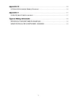
Page 5: ...ndix IV 56 I O Zone 583 Controller Battery Checkout 56 Appendix V 57 Control System Field Conversion 57 Typical Wiring Schematic 59 RECIRCULATING WDF MODEL DIAGRAM 59 NON RECIRCULATING WDF MODEL DIAGR...

Page 6: ...ntrol module via the Local Access Port see Figure 1 for the location of the Local Access Port The operating parameters for individual units may be input through the BACview A PC may also be connected...

Page 7: ...w station imparts unparalleled adaptability into the operation of each unit A daily self calibration enables AireLogic to detect the exact ratio of outside and return air entering the unit Then AireLo...

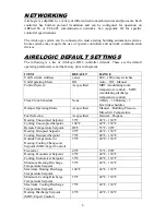
Page 8: ...erature control MDT modulating discharge temperature control Time Clock Schedule None 4 Daily 12 Holiday 2 Override schedules Damper Operating Mode As specified Manual Building Pressure Mixed Air Temp...

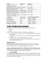
Page 9: ...methods for controlling the operating modes a remote control panel with one or two rotating adjustment knobs MRT and MDT controls an intelligent room sensor and BACview panel with LCD display MRT Expe...

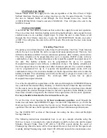
Page 10: ...in the Manual Mode rotate the temperature setpoint knob on the remote control panel clockwise to the desired discharge air temperature setpoint This will place the unit in the MANUAL mode and enable...

Page 11: ...programmed for up to 2 separate Occupied Unoccupied events with any combination of days The override schedule sets the Occupied times that will override the holiday schedule This scheduling system all...

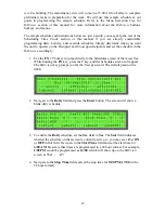
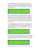
Page 12: ...edule in the BACview accordingly 1 Use the FN 7 hotkey to jump directly to the Schedules screen of the menu tree While holding the FN key press the 7 key and the Schedules screen will appear The BACvi...

Page 13: ...upied periods in the Holiday schedules The Unoccupied period we want to schedule then is from 6 00 AM to 8 00 AM and 12 00 PM to 5 00 PM We will use 10 Holiday schedules to accomplish this two for eac...

Page 14: ...room air temperature has risen 2 above the Heating Setback setpoint The default for this setpoint is 55 F To change the Heating Setback setpoint scroll through the SETPOINTS menu tree locate the Heat...

Page 15: ...ll place the unit in the AUTO mode This activates the four Auto mode functions Scheduling Time Clock The MDT EXPERT control does not support the night setback functions The primary Auto Mode function...

Page 16: ...ome in at 5 00 AM on Friday to complete preliminary tasks in preparation for the week We will use this sample schedule as our guide in programming the sample schedule Refer to the Menu Selection Tree...

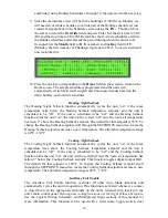
Page 17: ...elds except for SAT and SUN Your screen should now look like this 6 The week of Thanksgiving for 2012 is from Sunday November 18th to Saturday November 24th We want the unit to be On each weekday from...

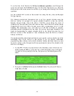
Page 18: ...hedules override the Holiday schedules and represent the period during which the unit is to be On Set the Month field to 11 November and the Day field to 19 Monday the first weekday of Thanksgiving we...

Page 19: ...nt knob on the remote control panel clockwise to the desired temperature The allowable temperature range is 55 F 90 F AireLogic units configured for MRT or MRT Expert controls will have a fixed discha...

Page 20: ...culate air before the burner and employ an airflow measuring station utilize a control scheme that measures air pressure to determine the ratio of outside air and return air These units are listed by...

Page 21: ...ge air temperature setpoint and the room air temperature is 5 F above the room air temperature setpoint This function is intended to restrain the room temperature from rising uncontrollably in buildin...

Page 22: ...line clockwise Once the room temperature has fallen to a temperature that is 2 F below the cooling setpoint the cooling and fan will be disabled Follow the dashed line downward If the room temperature...

Page 23: ...e ventilation mode Follow the dashed line downward If the room or outside air temperature falls to a temperature that is 2 F below the heating setpoint the heating will be enabled and the unit will be...

Page 24: ...cooling output to maintain the supply air temperature within a defined operating window This window defines the maximum and minimum discharge temperatures To change the desired minimum supply or disch...

Page 25: ...b on the remote control panel to the desired percentage of outside air If the unit served by this control is a direct fired heater that recirculates air before the burner and is operating in the heati...

Page 26: ...erature The allowable range is 30 F 90 F If the unit served by this control is a direct fired heater that recirculates air before the burner and is operating in the heating mode the unit will automati...

Page 27: ...100 outside air By physical design direct fired heaters that recirculate air after the burner supply a minimum of 25 outside air Freezestat The Freezestat function automatically cycles the unit off if...

Page 28: ...s for recirculating model units for typical connections of transducers The IN 2 configuration jumpers on the controller must be set for the appropriate input signal A contact closure between the appro...

Page 29: ...gic controller The controller compares this signal to the desired user control setpoint 75 F and uses the PID loop to modulate the output from 0 100 0 10Vdc The output is connected to the chilled wate...

Page 30: ...ntrol setpoint the output could increase from 0 to 100 as the input variable decreases from the User Control setpoint to the Min User setpoint In this situation the output value is the greater of the...

Page 31: ...y the PID control sequence or the override whichever is more Unit Resets This section should assist the user in resetting alarms and cycle counters which have been displayed on the BACview ALARM There...

Page 32: ...istory locate the Alarms page in the BACview menu tree The alarms history shows active alarms alarms that have returned to normal and manually cleared alarms CALIBRATE The Calibrate function forces th...

Page 33: ...sistor When a switch is closed the resistance at the controller input changes This allows the controller to identify which switch has closed The controller is programmed to associate each different re...

Page 34: ...or to shutdown check prior alarm log 1 Is the outside air OA Temp or room air Room Temp displayed on the BACview remote reading 150 F or more a Yes That sensor circuit or the sensor itself is shorted...

Page 35: ...rminal 2 Yes Continue 4 Is there 24VAC on the signal conditioner power terminals a No Determine cause and rectify b Yes Continue 5 Is there twice the DC voltage on the signal conditioner s output term...

Page 36: ...K See thermistor output curve for other temperatures If it is not open there is a break in the wiring between the sensor and the input plug Determine cause and rectify b No Continue 4 Reset the alarm...

Page 37: ...ion Contact the factory ALARM CODE Safety Circuit Open PROBLEM The controller has detected a failure in the safety circuit This alarm does not disable the burner and does not affect actual operation o...

Page 38: ...n in the wiring between these terminals Determine cause and rectify b Yes Replace controller ALARM CODE Burner Status PROBLEM The controller has activated the burner enable output but the burner statu...

Page 39: ...ller program Contact factory b No Continue 2 Are the main automatic gas shutoff valves energized a No The main automatic gas shutoff valves are leaking Turn off unit and close manual gas valves Determ...

Page 40: ...a signal that the fan is running This alarm will automatically clear about 15 seconds after the alarm is corrected SOLUTION If fan is running 2 Is controller unit enable output LED for lit a Yes There...

Page 41: ...the high and low velocity airflow switch contacts closed a No Are the belts on and is the fan motor 1 Yes Contact factory Do not adjust the switches setpoints 2 No Determine cause and rectify b Yes Co...

Page 42: ...is installed and continue b Yes Continue 3 Does the fan RPM match that listed on the Spec Sheet a No Correct to reduced fan speed and continue b Yes Continue 4 Are the airflow switches sensing tubes o...

Page 43: ...b No Continue 2 Are the airflow switch sensing tubes obstructed a Yes Clear and continue b No Continue 3 Is the airflow switch setpoint properly adjusted a No Adjust setpoint b Yes Continue 4 Are the...

Page 44: ...When 24VAC is powering the damper actuator and the control signal is 0VDC the outside air damper should be close to a rattle tight position and the return air damper should be open If the 24VAC power...

Page 45: ...has selected Mixed Air Temperature control mode for damper operation and the unit is configured for MDT or MDT Expert control or communications between the room sensor and the unit control module hav...

Page 46: ...unit s operation See BACview Equivalent temperature rise Simply stated this value is the actual temperature rise generated by the unit at any given time More precisely stated it is the quantity of ou...

Page 47: ...cess to the Unit Setup page requires the Admin Password Changes to the Unit Setup page after the unit leaves the factory can adversely affect unit operation in the field Do not make changes to the par...

Page 48: ...to check the program version number and whether the programs are initialized and running If the red error LED is flashing on the module a modstat is a useful troubleshooting tool Perform the modstat...

Page 49: ...0 Min Vent range 0 100 Htg Economizer Temp F range 40 130 Clg Economizer Temp F range 40 130 Freeze Stat F range 35 80 OA Temp for Htg Clg Changeover F range 40 130 Htg DA Temp F range 40 130 Clg DA T...

Page 50: ...d o Previous RESETS HOTKEY 6 Alarm Burner Reset Fan Count Cooling Reset Calibrate Home Schedules Clock Set Help SCHEDULES HOTKEY 7 24 hr Operation yes no Daily o Schedule1 typical 1 through 4 Use yes...

Page 51: ...Beg Mar 10 2013 End Nov 03 2013 o Beg Mar 09 2014 End Nov 02 2014 o Beg Mar 08 2015 End Nov 01 2015 o Beg Mar 13 2016 End Nov 06 2016 o Beg Mar 12 2017 End Nov 05 2017 o Beg Mar 11 2018 End Nov 04 201...

Page 52: ...the Unit Setup page requires the Admin Password Changes to the Unit Setup page after the unit leaves the factory can adversely affect unit operation in the field Do not make changes to the parameters...

Page 53: ...53 Appendix I 10K Thermistor Output Curve...

Page 54: ...54 Appendix II Airflow Station Layout...

Page 55: ...ATING RANGE 0 F to 130 F 10 to 95 RH non condensing INPUTS OUTPUTS 8 Universal Inputs Inputs 1 2 o Dry thermistor 0 5VDC Inputs 3 6 o Dry thermistor Inputs 7 8 o 1k 10k pot 5 Digital Outputs Relay con...

Page 56: ...th or so to verify that its voltage is approximately 3 VDC If the voltage is not approximately 3 VDC replace the battery so that the controller s program is not lost during a power outage Loss of the...

Page 57: ...oom sensor connected 2 Disconnect the unit enable potentiometer from terminals 214 215 and 216 and place a jumper between terminals 213 and 216 on the main terminal strip MDT Expert 1 Order a BACview...

Page 58: ...parameter on Unit Modes screen of BACview to MDT 3 Disconnect the BACview remote panel from the local access connection on the front of the unit control module MDT Expert 1 Change the Control System...

Page 59: ...59 Typical Wiring Schematic RECIRCULATING WDF MODEL DIAGRAM...

Page 60: ...60 NON RECIRCULATING WDF MODEL DIAGRAM...

Reviews: