


SKY899
Installation Manual
Page 2-22 - Installation
009-11900-001
July 18, 2013
Revision F
2.7 AIRCRAFT DISCRETE INPUTS
The aircraft discrete inputs are used for ViP™ extended audio callout, audio suppression and to assist in
determining the aircraft's phase of flight or flight condition (e.g., on ground or in flight). The discrete
inputs are configured in the service menu and saved to the System Configuration Module. There are three
service menu options, none, active low (electrically ground, 0 V dc to 2.0 V dc) and active high
(electrically high, +9 V dc to +28 V dc) for each input. The inputs are diode isolated inside the TRC, do
not install isolation diodes externally. Refer to appendix A for signal characteristics.
2.7.1
ViP™ Extended Audio Callout
The SKY899 must have software version 1.8 (or higher) and Mod D installed in order to use this feature.
In order to enable extended audio callouts, connect P1-32 (EXT_AUDIO_SW) to ground via a pilot
operated switch. When the pilot operated switch is in extended mode the TA aural alerts will have “range,
relative altitude (when available) and relative bearing” information announced as well as traffic. When
the switch is in the “Normal” position it mutes the range, relative altitude, and bearing callout from the
aural TA’s, but the standard phrase “Traffic, Traffic” is still annunciated.
CAUTION
Do not connect a switch to the extended audio switch input
(EXT_AUDIO_SW, P1-32), unless the TRC899 has Mod D and
Software Version 1.8 or higher.
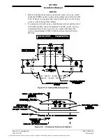
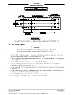
Any SPST switch (1/2 A @ 28 V dc) can be connected to P1-32 (see notes on Figure 2-2, 2-3 or 2-4).
Extended Audio Callout Switch connection:
EXT_AUDIO_SW
P1-32
2.7.2
GPWS (Audio inhibit)
The audio inhibit input will sense a terrain warning alarm (i.e., GPWS, EGPWS, TAWS) and temporarily
delay the audio alert output until the terrain warning clears. The input can be either a constant flag signal
or an alternating flag signal. The flag must be cleared for 5 seconds before the TRC accepts a “NO
ALARM” condition and restores audible alerts.
NOTE
If the aircraft is equipped with terrain warning system the GPWS,
EGPWS, or TAWS flag must be connected to the TRC.
GPWS connection:
GPWS P1-34
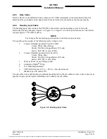
2.7.3
Landing Gear
This input is to be connected to the landing gear switch to sense the position of the landing gear (fixed, up
or down). If the aircraft does not have a landing gear switch (e.g., fixed-gear aircraft), leave this input
unconnected. With this configuration, if a radio altimeter (analog or ARINC-429) is not installed, the
system will default to the highest TA sensitivity level (level B) and audio TA announcements (i.e.,
“traffic, traffic”) will not be inhibited during takeoff and landing.
Landing gear connection:
GEAR P1-33
The document reference is online, please check the correspondence between the online documentation and the printed version.