


SKY899
Installation Manual
Page A-12 - Appendix A
009-11900-001
July 18, 2013
Revision F
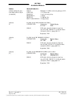
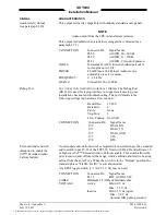
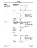
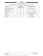
SIGNAL
CHARACTERISTICS
System Configuration
Module (Continued)
CONNECTION
Connector-Pin
Signal Name
P1-2
3.3V
P1-92
PLUG_GND
P1-99
SDA
P1-100
SCL
CABLE
Minimum 22 AWG wire for lengths up to 30 ft.
Vertical Sync
Balanced vertical sync from the WX-1000 Processor (if installed) and
output to the display. Signal levels as specified in RS-422.
CONNECTION
Connector-Pin
Signal Name
P1-30
V From Processor
P1-41
VSYNC_IN- From Processor
P1-13
VS To Display
P1-22
VSYNC_OUT- To Display
CABLE
See paragraph 2.6.7
VOLTAGE
0-5 V dc
FREQUENCY
60 Hz
SOURCE Z
1 k
Ω
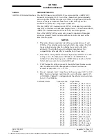
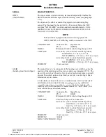
Video Output
Balanced video from the WX-1000 Processor (if installed) and output to
the display. Signal levels as specified in RS-422 specification.
CONNECTION
Connector-Pin
Signal Name
P1-35
V From Processor
P1-36
VIDEO_IN- From Processor
P1-16
VI To Display
P1-17
VIDEO_OUT- To Display
CABLE
See paragraph 2.6.7
VOLTAGE
0-5 V dc
CURRENT
<100 mA
FREQUENCY
<15 MHz
LOAD Z
1 k
Ω
WX-1000/SKY497 Display
Power supply to WX-1000/SKY497 display. +15/-15 V dc from the
Display
Power
WX-1000 Processor (if installed) and output to the display.
CONNECTION
Connector-Pin
Signal Name
P1-25
DPWR+15_IN From Proc.
P1-26
DPWR-15_IN From Proc.
P1-27
DSPLY_GND_IN From Proc.
P1-8
DPWR+15_OUT To Display
P1-9
DPWR-15_OUT To Display
P1-10
DSPLY_GND_OUT To Display
CABLE
See paragraph 2.6.7
VOLTAGE
+15/-15 V dc
CURRENT
0.7 A input max.
The document reference is online, please check the correspondence between the online documentation and the printed version.