


SKY899
Installation Manual
009-11900-001
Appendix D - Page D-1
Revision F
July 18, 2013
Appendix D
Installation Checkout
Using the TIC T-49C Flightline Tester
D.1 INTRODUCTION
This section contains checkout procedures that will validate the installation and return to service of the
SKYWATCH® HP SKY899 using the TIC T-49C Flightline Tester. Detailed setup, operation and
maintenance information for the T-49C Flightline Tester is provided in the T-49C Operating and
Maintenance Instruction Manual.
CAUTION
Each time the TRC, directional antenna, or directional antenna cables
(including connectors) are installed, removed or replaced, the TRC must be
calibrated to the directional antenna (refer to paragraph 3.3.2 & 4.4.3).
NOTES
1. This procedure assumes familiarity with the set up and operation of the T-49C
Flightline Tester.
2. All test equipment used in completing these tests shall be calibrated in
accordance with the manufacturer's recommendations.
3. When the SKY899 is interfaced to an alternate display, reference Appendix F
while performing this checkout procedure.
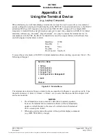
D.2 CONTROLS
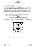
All operating controls are located on the front of the WX-1000/SKY497 display. Figure D-1 shows the
locations of the controls. Complete operating instructions for the SKY899 are provided in the SKY899
Pilot's Guide supplied with each system.
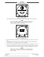
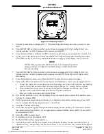
Figure D-1: Controls
OFF/BRT Switch
Power is applied by rotating the knob clockwise past the detent. Continued
clockwise rotation increases display brightness.
1, 2, 3, & 4 Pushbuttons
Also referred to as soft-keys (1), (2), (3), and (4). In every operating mode a
label identifying the button function will be displayed next to the button.
The document reference is online, please check the correspondence between the online documentation and the printed version.