SKY899
Installation Manual
009-11900-001
Installation - Page 2-3
Revision F
July 18, 2013
2.4 TRC LOCATION
Typically the TRC is installed in the electronics bay. In selecting a location, consider the following:
Cable Length
Cable runs should be as short as practicable in order to minimize potential
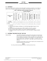
electrical interference. Cable length to antennas must not exceed the values listed
in table 1-9.
Cooling
While the TRC has no special cooling requirements, it should be mounted to
permit adequate ventilation. Caution should be observed to not inhibit airflow
from the rear mounted fan. Allow at least three inches (8 cm) of rear clearance.
Pressurized Aircraft
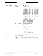
The TRC may mount inside or outside the pressure vessel. The TRC contains no
batteries or potentially explosive components and will operate up to 55,000 ft.
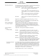
Memory Card Access The TRC is equipped with a front access memory card connector port intended
for use with compact flash cards. This connector port may be used for system
configuration, future software upgrades and data recording. In order to insert and
extract the memory card (without removing the TRC from its mounting tray),
clearance must be maintained for the access door to open and permit space for
the installer's hand.
2.5 DISPLAY LOCATION
The display should be mounted in a location easily accessible and clearly visible to the pilot. If using an
alternate display device refer to manufacturer instructions for location. In selecting a location for WX-
1000/SKY497 display, consider the following:
Magnetic Effect
Where possible to avoid it, the display should not be mounted within 3 inches (8 cm)
of an electric turn and bank indicator, as the magnetic effect of the turn and bank
motor may affect the display presentation. (A common symptom of magnetic
interference is a wobbling or vibrating display raster.)
NOTE
If it is necessary to mount the display unit next to a device that may
affect the CRT display, magnetic shielding material can be placed around
the display unit. Shielding material is available from L-3 Avionics
Systems. Specify P/N 78-8060-5882-8 when ordering.
Panel Depth
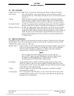
Adequate depth must be available behind the instrument panel to allow for the
display, the display connector, and excess display cable. Remember that a service
loop is necessary to allow access to the display connector when removing the display
or inserting it into the instrument panel.
Cooling
While the display has no special cooling requirements, it should be mounted to
permit adequate ventilation.
Viewing Angle
The viewing angle for the CRT display is not a critical factor. The most favorable
mounting position would be near eye level and no more than arms length from the
principle user of the instrument.
The document reference is online, please check the correspondence between the online documentation and the printed version.


