SKY899
Installation Manual
Page H-2
Appendix H - 009-11900-001
July 18, 2013
Revision F
Figure H-2: IFR-6000 Test Set Basic Controls
1 – Multi-function soft-keys.
2 – Data Buttons. Moves screen curser up and down, left and right.
3 – Power Button, green. Once power has been applied, a green light will display above the power button.
4 – Display Controls. Adjusts screen contrast or backlight. Use data buttons (2) to increase or decrease
values.
5 – RANGE Buttons. Increase or decrease TCAS range.
6 – RATE Buttons. Increase or decrease TCAS rate.
7 – SETUP Button. Displays setup screens for the selected mode.
8 – TCAS Button. Access TCAS mode functions.
H.3 CHECKOUT PROCEDURE
The IFR-6000 flight line tester simulates ATCRBS Mode C or Mode S intruders by manually defining a
scenario and can then verify the correct Traffic Advisories and Resolution Advisories have occurred on
the SKY899 display. Intruding flight patterns are programmed from the IFR-6000 TCAS screen using the
following procedure:
1.
Mount the IFR-6000 directional antenna on the IFR-6000 test set then connect the short (12 in.) RF
coaxial cable between Antenna Connector and Test Set ANT Connector.
2.
Press the Green POWER button to turn the test set ON.
3.
Press the TCAS mode select button on the IFR6000 to enter the TCAS screen.
4.
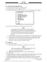
Press the Setup button (under the TCAS button) to enter the TCAS Setup screen (Figure H-3).
Figure H-3: TCAS Setup Screen
The document reference is online, please check the correspondence between the online documentation and the printed version.


