P 4.1
SECTION IV
Adjustments
A. ADJUST BRUSH TRACKING.
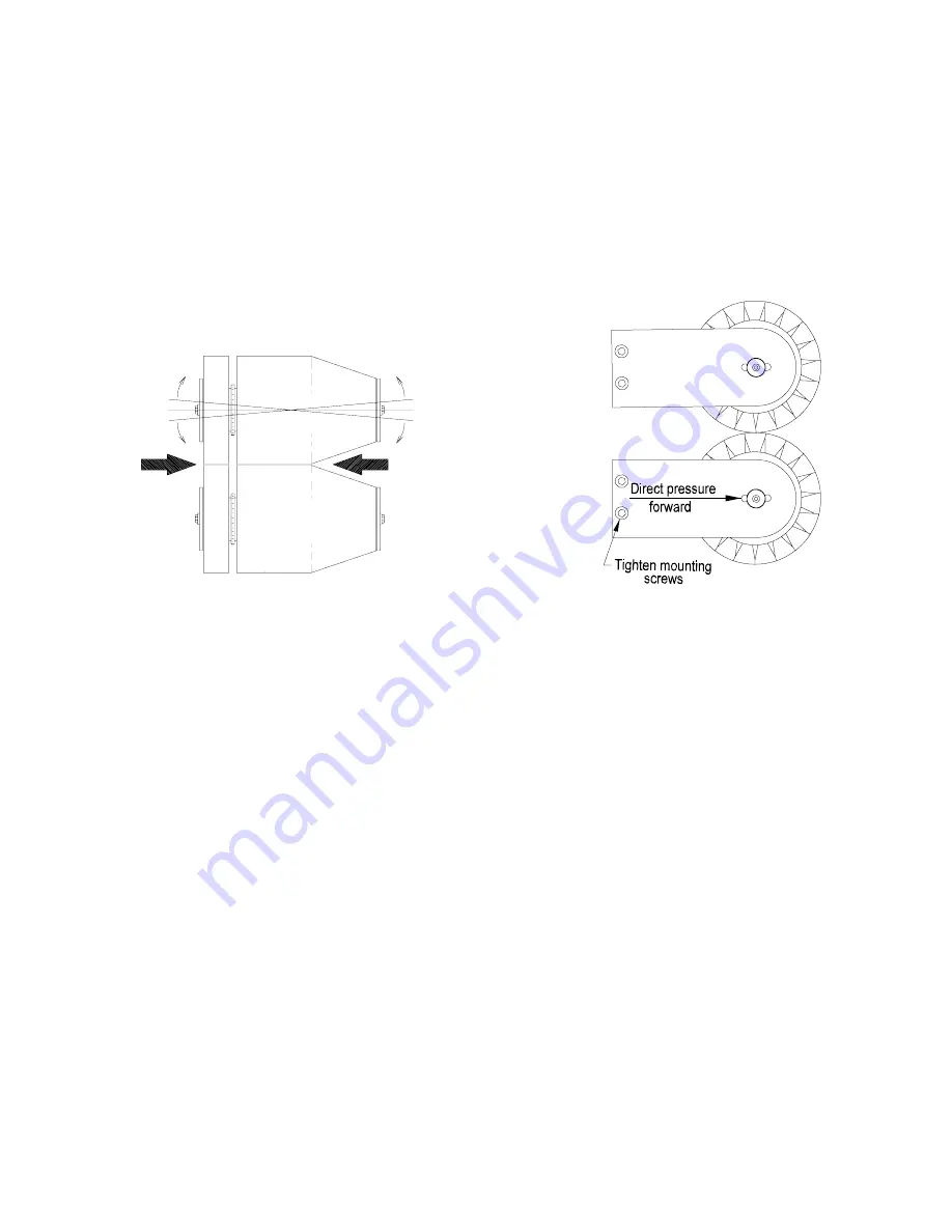
Figure 4.1 and 4.2
The bagneck should be as flat and wrinkle free as
possible as it enters the closer. The two brush assem-
blies should be parallel where they contact to optimize
the tensioners ability to prepare the bagneck for entry
into the closer. (Figure 4.1) The brush mount plates
mount with two 10-24 x 1/2" socket head cap screws.
These screws are used to align the brushes as follows.
1.
Loosen the two plate mounting screws on the
side of the brush assembly to be aligned.
2.
Hold the brush mount plate in your hand.
3.
Apply pressure to the back of the plate (opposite
the curved end) in a forward direction toward the
brush assembly (Figure 4.2).
4.
Raise or lower until the brush mount plate is
pressed firmly against both mounting screws.
(The mounting holes are oversized allowing for
this adjustment) Tighten the mounting screws.
5.
From the front of the tensioner check the gap
between the two brush assemblies and verify
that they are now parallel (this does not apply
to the tapered portion of brush assembly).
6.
If needed, repeat the adjustment.
CAUTION: DISCONNECT POWER TO THE
BAG TENSIONER BEFORE CONDUCTIONG
ADJUSTMENTS.
J8S 06 04
Figure 4.1
Figure 4.2


