Troubleshooting Electrical Problems
6-25
KVAL 994-X Operation/Service Manual
Troubleshooting Electrical Problems
Refer to Air and Electrical Schematics provided with delivery of the
machine. Schematics are located in the Electrical Panel. If copies
are unavailable, contact the KVAL Service Department. Have
model number and serial number of machine readily available.
NOTE:
The following checks require the electrical panel to be energized. These
troubleshooting checks
must
be performed by a
Qualified Electrical
Technician.
Warning
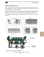
The electrical component systems are designed to expedite the troubleshooting process and mini-
mize “down time”. In general, component systems have the input or feed functions at the top.
Output or load functions are positioned at the bottom. Most two-voltage electrical panels are
designed with the LOW VOLTAGES on the LEFT, and the HIGH VOLTAGES on the RIGHT.
The majority of the system components are labeled with numbers that correspond with the electri-
cal prints included in the electrical box door.
Computer controlled machines have signals on the computer that light up when the input or out-
put functions are energized, respectively. Computer controlled as well as non-computer controlled
machines have white 120V control power terminal strips. This will indicate power supply from
the respective circuits.
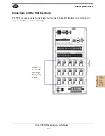
PLC controllers also have lights on them for the input and output functions. You can easily find
out which circuits are failing by watching the lights turn on or off. Compare the lights on the
IDEC or Beckhoff controllers to the electrical print to determine what systems are being affected.
If the Power Stops During Normal Operation
1.
Check that the input power disconnect switch is not turned off.
2.
Check that all of the emergency stop buttons are in the normal position.
3.
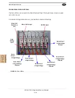
Check the Six Lights on the Electrical Panel. See “Troubleshooting with the Status
Lockout and Tagout the main power source.
1.
Turn the panel disconnect switch in the off position, open the electrical panel door.
2.
Observe the disconnect switches. Look for loose or broken wires at the disconnect
then at all of the components.
3.
Check for continuity of all fuses with an OHM meter. (Fuses need to be removed
from the bottom side of the fuse holder before measuring the fuses)
Summary of Contents for 994-X
Page 4: ...KVAL 994 X Operation Service Manual ...
Page 31: ...Safety Sign Off Sheet 1 21 KVAL 994 X Operation Service Manual ...
Page 32: ...Safety Sign Off Sheet KVAL 994 X Operation Service Manual 1 22 ...
Page 110: ...Calibration of the Back Section KVAL 994 X Operation Service Manual 3 22 ...
Page 114: ...System IT Administration KVAL 994 X Operation Service Manual 4 4 ...
Page 144: ...Collet Torque Values KVAL 994 X Operation Service Manual 5 30 ...
Page 180: ...Symptoms and Possible Causes KVAL 994 X Operation Service Manual 6 36 ...
Page 185: ......
Page 186: ......
Page 187: ......


