


XPS-E
28 / 36
Cabling
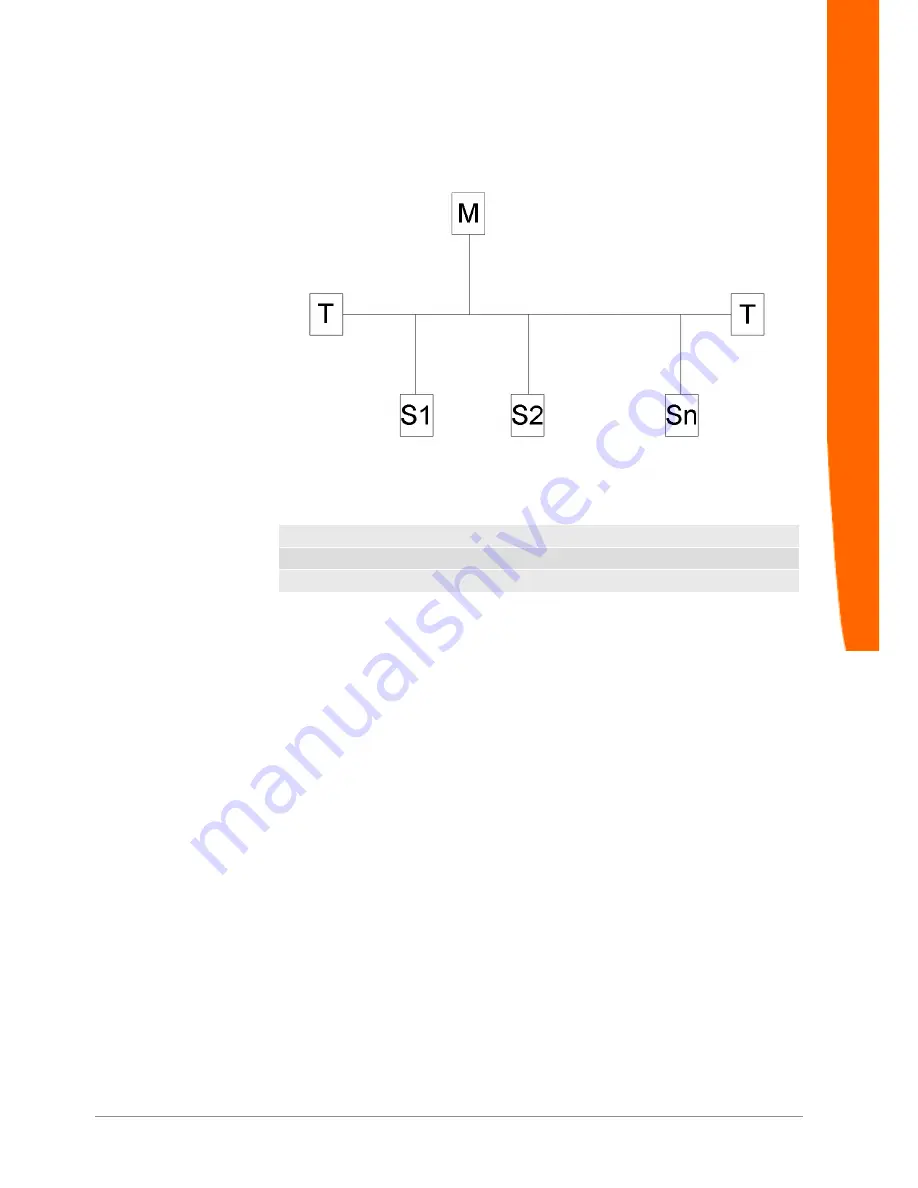
Illustration 10:
Connection of a PROFIBUS-DP Slave within a Segment
T= Terminator
M= Master
S= Slave n<31
If no terminator with independent power supply shall be used (active
terminator), the termination must be realised directly at the last
stations of the bus. This station must then supply the terminator with
power. For details regarding the PROFIBUS installation please refer
to the PROFIBUS Installation Guidelines of the PROFIBUS User
Organisation (PNO, Order No.: 2.112).
Connector Assignment and Cabling


