7
CAUTION: Inspect all chimney components for damage. Do not use any damaged chimney
components.
1.
Familiarize yourself with the clearances of the stove for the configuration in which you have
chosen to install, i.e. corner installation or straight wall installation (see section 6). Notice the
clearances listed for the chimney, this will help you determine the location of the hole in the
ceiling. Note: On metal roofs in snow regions, consideration must be given to snow loads above
the chimney that can slide in to chimney and severely damage it. Please consider snow breaks or
snow dividers to prevent damage.
2.
Once you’ve determined the stove location based on the applicable clearances and connector type
(see section 6), be sure to check attic and roof for any obstructions. Install the chimney system
according to the step by step illustrated instructions that came with your chimney.
3.
Special care needs to be exercised when passing the chimney through an attic space. An attic
insulation shield must be used in all chimney installations to ensure that no insulation can contact
the chimney pipe. If there is little or no attic space, or if you have a vaulted ceiling, use a tall
square cathedral ceiling support box to pass all the way through to the roof line to provide the
shielding.
4.
Stability: If necessary, install a roof brace kit on the chimney to stabilize the chimney against
wind, etc. Generally, roof bracing is required if the chimney extends more than five feet above the
chimney exit point.
5.
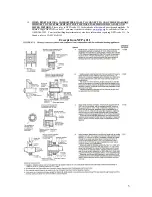
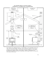
See illustrations in section 6 for all components required for factory-built chimneys, as well as
parts required to connect to an approved masonry chimney.
6.
Chimney Height. The Installation Diagram in section 6 shows the minimum chimney height in
relation to the roof. With low pitch roofs or little attic space, the chimney can be too short. For
proper draft and best performance, a minimum overall height of connector pipe plus chimney
combined should be at least 12 feet tall, measured from the stove top to the chimney cap. If
necessary, add chimney.
STEP 3: OUTSIDE AIR SUPPLY
Outside Air –
An
outside air supply is required in all manufactured/mobile home installations.
1.
Kuma stoves does not particularly require that outside air be directly connected to this
stove,
However, some state or local building codes may mandate outside air. If your state or
local building code requires an outside air supply use part# KA-OUTSIDEAIR-2. If you are
unable to supply a direct connection to the stove or if you need additional ventilation due to room
air starvation, we suggest the following:
a.
Provide a passive air supply to the home. The air vent should be a minimum of 3” in
diameter.
b.
The air supply must be provided to the same room that the stove is installed in.
c.
The air supply should utilize a barometric damper so that air is only supplied to the room
if the house pressure becomes negative.
Visit
www.woodheat.org
for more information on the use of outside air.
2.
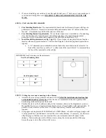
When building a hearth pad on site, be sure to leave an area open for the installation of the
outside air vent.
Once the hearth is positioned according to the minimum clearances, locate and
mark out the hole for the 3” outside are vent. On a pedestal model stove, this hole may be
anywhere under the stove base. On a leg model stove, try and locate the hole to line up with the
hole in the bottom of the stove. On a pre-manufactured hearth, use a hole saw or circular saw to
cut through just the backing board then use a hammer and firmly hit the tile or stone on the top
side. If the backing board was cut to the correct depth, the tile or stone will break out very clean.
Also using a hole saw or circular saw cut the hole through the home floor into the crawl space. Be
sure to line this hole up with the one in the hearth.


