- 13 -
P.T.O. DRIVE SHAFT
Make sure the rotary harrow is resting on the ground and is maintained in a stable position with the rollers. Install
the PTO shaft making sure that the clamp yoke is on the machine end. Tighten both M 16 bolts to 22 daNm / 160
ft.lbs. Tightness has to be checked regularly.
After mounting the rotary harrow, stabilize the tractor 3-point linkage with whatever means are recommended i.e.
the bars, chains, etc.
Be sure the tractor P.T.O. shaft drive is disengaged and stop engine.
Couple the P.T.O. shaft to the tractor P.T.O stub.
Attachment is correct when machine is horizontal in work position.
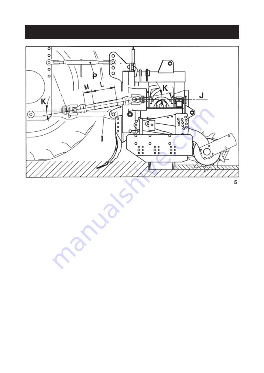
With the machine resting on the ground, adjust the top link (P) length to a position where the tractor PTO stub and
the tiller input shaft are parallel.
In working position :
- The 2 angles (K) formed by the centre lines of the yoke and the sliding tubes must be equal and not exceed a
combined angle of 30° when working.
- The sliding tube overlap (L) must be at least 22 cm (8.5") (fig. 5).
With the machine fully raised on the tractor hydraulic linkage :
- The 2 sliding tubes must not completely overlap each other ; a gap (M) of 1 cm (3/8") should exist between end
of sliding tube and yoke.
- Both U joints (K) should operate approximately at the same bent angles which must never exceed 40° (fig. 5).
Should the above mentioned conditions not exist :
- Shorten both tubes by an equal length, chamfer edges and grease liberally before refitting.
- To avoid noisy running of the PTO shaft when lifting the machine out of work, attach top link (P) so that it is almost
parallel to the lower links (
I
) (fig. 5).
Important : Always disconnect the tractor PTO drive before lifting the machine into the transport position,
otherwise permanent damage can be caused to the transmission shaft.
Repeat these adjustments each time the machine is mounted to a different tractor.


