9
MOWER MOUNTING
ENGLISH
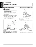
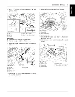
8. Put a 14 mm (0.55 in.) shaft in the hole in the rear
right side lift link.
A
Use a shaft more than 150 mm (6 in.) long.
A
It passes through a hole in the frame.
9. Attach the lift links to the mower deck with attaching
hardware.
10. Remove the 14 mm (0.55 in.) shaft from the hole in
the rear right side lift link.
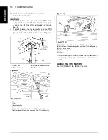
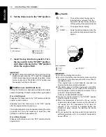
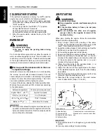
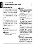
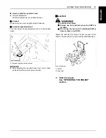
11.Attach the mower belt to the PTO clutch pulley.
12.Remove the step.
(See "HOW TO OPEN THE STEP" in "PERIODIC
SERVICE" section.)
13.Turn the tension arm counterclockwise with a square
wrench.
(1) Shaft
(2) Lift link
(3) Frame
(D) 14 mm (0.55 in.)
(L) More than 150 mm (6 in.)
(1) Lift link
(2) Clevis pin
(3) Plain washer
(4) Snap ring
(P) OUTSIDE
(1) Mower belt
(2) PTO clutch pulley
(1) Tension arm
(2) Mower belt
(3) Mower pulley
(A) Square wrench
(P) "COUNTERCLOCK WISE"
Summary of Contents for Z723
Page 7: ......
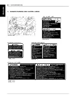
Page 13: ...SAFE OPERATION 6 ENGLISH 5 DANGER WARNING AND CAUTION LABELS ...
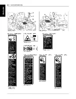
Page 14: ... 7 SAFE OPERATION ENGLISH ...
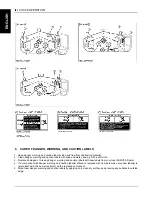
Page 15: ...SAFE OPERATION 8 ENGLISH ...
Page 16: ... 9 SAFE OPERATION ENGLISH ...
Page 19: ...SERVICING OF MACHINE 2 ENGLISH 1 ROPS serial No ...


