


Inspection Guidelines for Plasma
®
Synthetic Ropes
Puget Sound Rope Company
1012 Second Street
Anacortes, WA 98221
USA Telephone:
360-293-8488
Fax:
360-293-8480
www.psrope.com
email: [email protected]
Plasma ropes have been used extensively in numerous diverse applications for many
years. Over this time period, particular operating conditions and hazards have been identified
which are more harmful to Plasma than to steel. The presence of these conditions can
best be determined by periodic inspection of the lines. This guideline presents
recommendations for conducting periodic inspection by the end user
Conditions to be avoided in Plasma Lines
There are three areas where close attention needs to be paid to Plasma lines. Below are
descriptions of these conditions and likely signs of their presence.
1. Repeated lateral abrasion against sharp edges. While HMPE is one of the most cut-
resistant polymers available, metal can prove to be stronger than Plasma in a long-
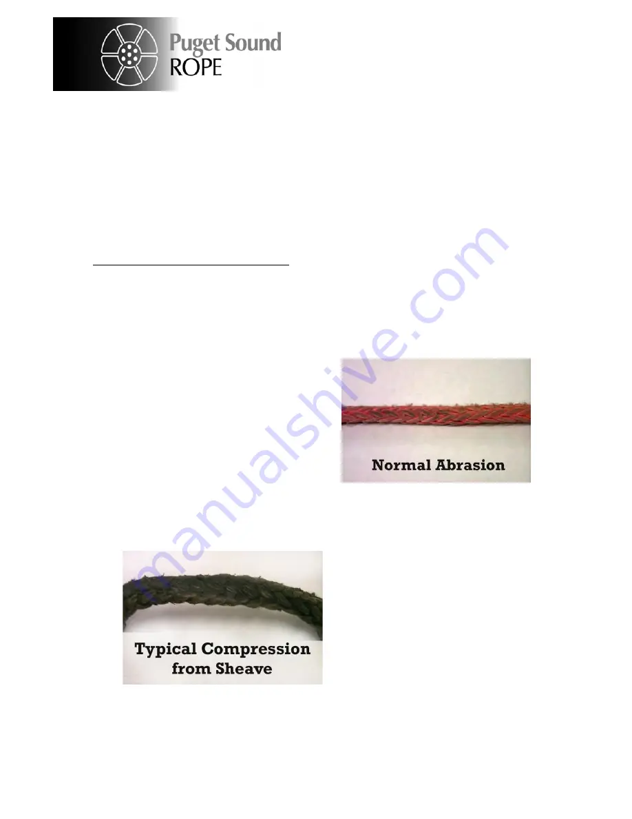
duration abrasion event. Signs of excess
abrasion include strand pullouts, heavy
fuzzing and cut strands in a single area,
and localized bunching. It should be
noted that normal light fuzzing of the
Plasma rope surface is to be expected in
normal use. This light fuzzing does not
reduce the rated strength of the line, and
actually creates a protective layer on the
rope that helps to prevent further damage.
2. Plasma begins to lose strength above about 160 ºF, and has a zero-strength temperature
around 250 ºC. Signs of high temperature damage include, melting, fused strands, and
significantly reduced diameter. The fused
strands should not be confused with
high-tension compression of the rope
which might appear similar. With
standard urethane coatings, the rope can
appear melted after high tension has been
applied while the rope is bent around a
surface. This is normally not melting and
can be worked out with little effort. The
rope strength is not affected.
3. Plasma lines can lose strength if overstrained. This can be the result of exceeding the
recommended design factor for an extended time period, or by instantaneous peak
loads during dynamic loading events. A typical design factor is 5:1, but this should be
determined in conjunction with the application engineer. Signs of overstraining can be
subtle but include localized thinning and elongation, and loss in flexibility (for example
the rope becomes rigid).
Page
1
9
Summary of Contents for Impac 500
Page 28: ...IMPAC 500 NOTES Page 26 ...


