code R30020.100en www.kseniasecurity.com
ed.04/2020
OUTPUTS WORKING MODES
Both in stand-alone or directly connected to the Panel, the relay outputs can be programmed as follows:
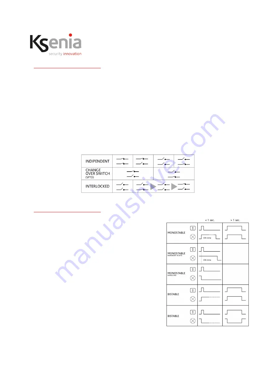
• INDIPENDENT OUTPUTS
: both the outputs are completely independent and can be separately
programmed (eg. the first output as bistable and the second one as monostable).
• STPD (change over switch) OUTPUTS
: the outputs are considered as an unique logic output. The first is
Normally Open and the second one is Normally Closed. The outputs are dependent and cannot be
separately managed. The commutation of the first relay implies the commutation of the second one.
• INTERLOCKED OUTPUTS
: in this mode, particularly useful to manage electric motors, the relay outputs
cannot be active at the same time. In case an output is active and the other one has to be activated, both
of the outputs will be deactivated for half a second and then will commutate.
The outputs can be programmed as Bistable or Monostable, regardless the selected configuration.
OUTPUTS MANAGEMENT THROUGH LOCAL CONTACTS (STAND-ALONE | LARES 4.0)
What follows is valid only for using auxi wls as stand-alone device
or as peripheral on Panel, without associated zones (see above).
In case of independent or interlocked outputs, the first input
manage the first relay output and the second input manage the
second relay output. In case of STPD (change over switch) output
it is possible to use one or another input to manage the output.
At the changing of the inputs status, outputs react as follows:
• MONOSTABLE OUTPUT
: If the input remains closed for less
than one second (use with short press of button), the output
is activated during the ON time. In case the output is already
active, the ON time is restarted, if the output is programmed
as independent or SPTD (change over switch). Otherwise the
ON time turns off, if the output is programmed as interlocked.
If the input remains closed for more than one second (use with
long press of button), the output commutates both at the
closure and at the re-opening of the input.
• BISTABLE OUTPUT
: If the input remains closed for less than one
second, the output commutates only at the input closure. If the
input remains closed for more than one second, the output
commutates both at the closure and at the re-opening of the input.


